Touch screen contoller and method for controlling thereof
- Summary
- Abstract
- Description
- Claims
- Application Information
AI Technical Summary
Benefits of technology
Problems solved by technology
Method used
Image
Examples
first embodiment
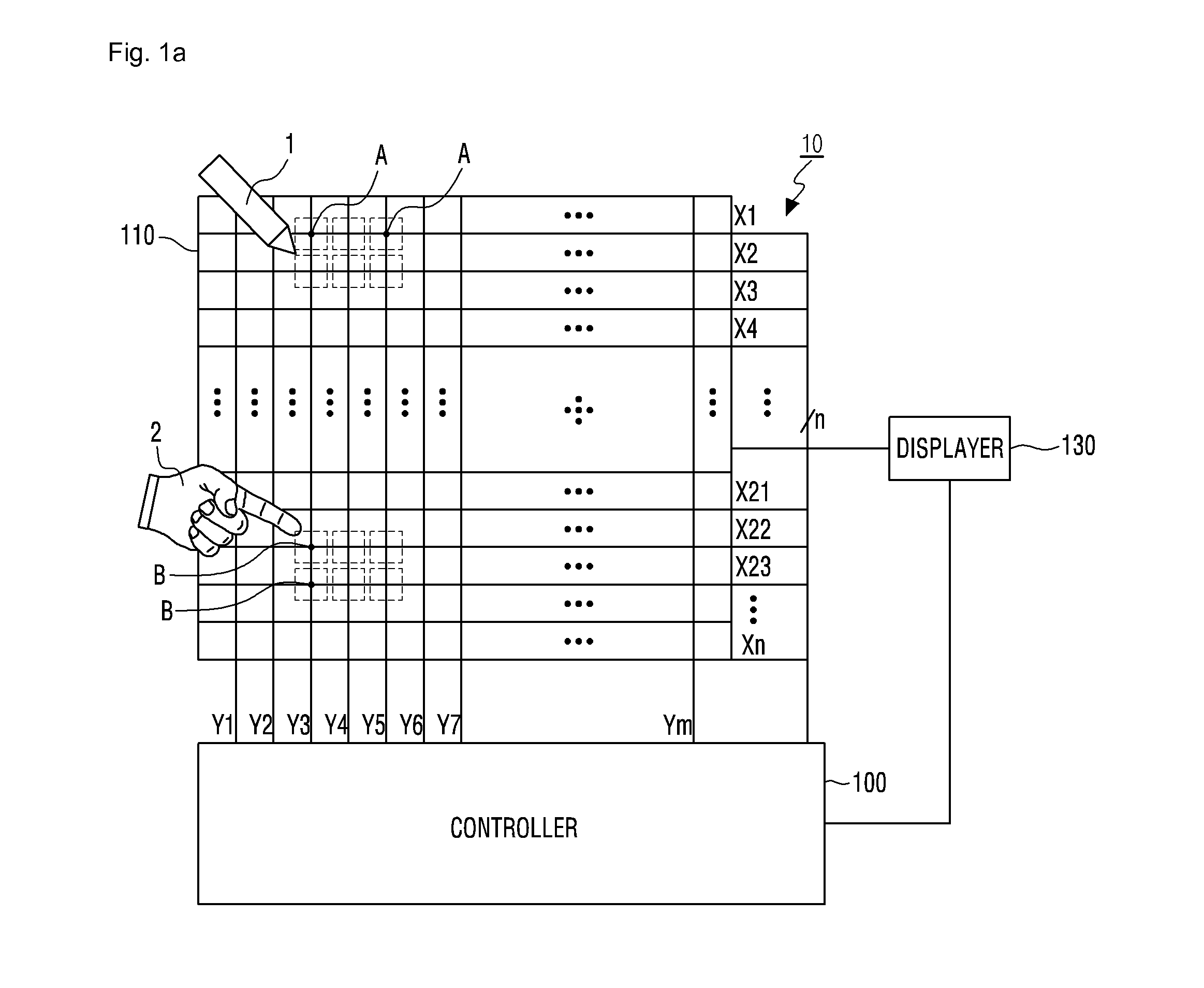
[0112]FIGS. 9a to 9c are conceptual views showing how the touch processor shown in FIG. 1a displays a line on a displayer.
[0113]Referring to FIGS. 9a to 9c, as shown in FIG. 9a, the controller 100 may cause certain lines 10a, 11a, and 12a to be displayed on the displayer 130 in accordance with the first touch action mode. The controller 100 may control the thickness of the line which is displayed on the displayer 130. The thickness of the line may be determined by sensing the pressure applied to the touch panel 110. That is, when a high pressure is applied to the touch panel 110 by the object, the line may be displayed thick like the line 10a, and when a low pressure is applied to the touch panel 110 by the object, the line may be displayed thinly like the line 11a. The lines displayed on the displayer 130 may cross each other like the lines 11a and 12a. When the lines 11a and 12a cross each other, the crossing P1 may be displayed thicker than a point where the lines do not cross ea...
second embodiment
[0115]FIGS. 10a to 10d are conceptual views showing how the controller shown in FIG. 1a displays a line on the displayer.
[0116]As shown in FIGS. 10a and 10b, the controller 100 may cause a pressure gauge 21 to be displayed on one side of the displayer 130 by using a pressure information field of the touch signal, which corresponds to the pressure signal of the pressure sensor 120. In the embodiment, the application processor 220 included in the controller 100 may cause the pressure gauge 21 to be displayed on one side of the displayer 130. Through use of the pressure gauge 21, the user is able to recognize the pressure applied to the touch panel by the object. The pressure gauge 21 is displayed with scales. However, there is no limit to this. The pressure gauge 21 may be displayed in the form of a bar and the pressure may be displayed in response to the length of the bar. Also, as shown in FIGS. 10c and 10d, the controller 100 may cause a window 22 and 23 to be displayed on one side...
third embodiment
[0117]FIG. 11 is a conceptual view showing how the controller shown in FIG. 1a displays a line on the displayer.
[0118]Referring to FIG. 11, when at least a portion of a line 10d is removed through the second touch action mode after the line 10c is displayed on the displayer 130 through the first touch action mode, the controller 100 may cause the removed portion to be indicated by a dotted line, and the user is allowed to restore the removed portion by touching the shortest distance between the start point P21 and the end point P31 of the removed line. The removed portion can be restored by displaying all of the signals having the same index through use of the index field included in the touch signal. When the information on the coordinate value of the removed portion is stored in the memory 340 and a restoration signal is generated by the controller 100, the line can be restored by using the information on the coordinate value of the removed portion stored in the memory 340. When a...
PUM
 Abstract
Description
Claims
Application Information
 - R&D
- Intellectual Property
- Life Sciences
- Materials
- Tech Scout
- Unparalleled Data Quality
- Higher Quality Content
- 60% Fewer Hallucinations
Browse by: Latest US Patents, China's latest patents, Technical Efficacy Thesaurus, Application Domain, Technology Topic, Popular Technical Reports.
© 2025 PatSnap. All rights reserved.Legal|Privacy policy|Modern Slavery Act Transparency Statement|Sitemap|About US| Contact US: help@patsnap.com


