
Trench interconnect having reduced fringe capacitance

a fringe capacitance, interconnect technology, applied in the direction of electrical apparatus, semiconductor devices, semiconductor/solid-state device details, etc., can solve the problems of degrading adhesion, mechanical properties such as the young's modulus, cohesive strength, and the increase of dielectric materials. to achieve the effect of reducing capacitance and maintaining structural stability

Active Publication Date: 2015-06-11
IBM CORP +1
View PDF6 Cites 19 Cited by
  • Summary
  • Abstract
  • Description
  • Claims
  • Application Information

AI Technical Summary

Benefits of technology

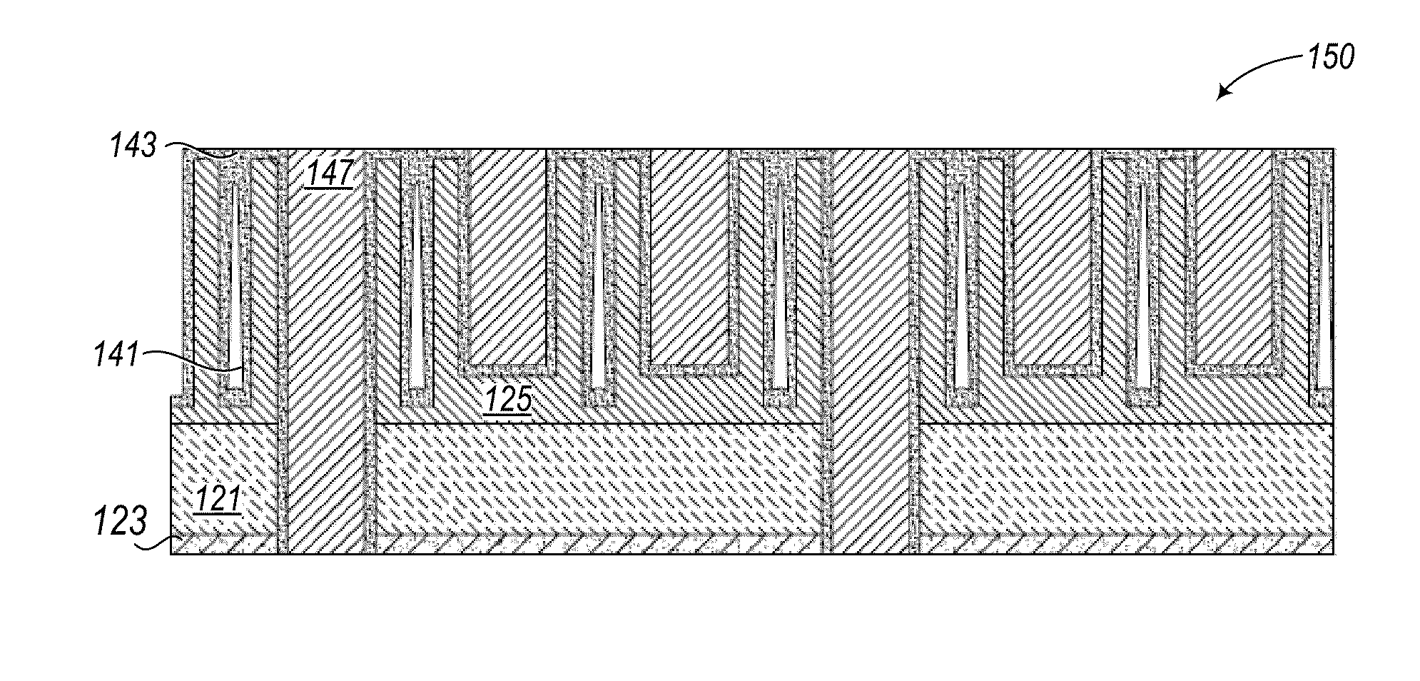
The patent text describes an advanced damascene interconnect structure for microelectronic circuits that reduces capacitance between adjacent nanowires while maintaining structural stability. This is achieved by incorporating a high modulus insulator with deep air gaps sealed by a high aspect ratio film. This interconnect structure has a lower effective dielectric constant and is suitable for use between metal-filled trenches and vias. The fabrication method involves patterning dielectric U-shaped structures with deep air gaps and metal trenches using a hard mask. The technical effects include improved performance and reliability of microelectronic circuits.

Problems solved by technology

However, as the dielectric constant of such materials is reduced below a value of about 2.4 to achieve better electrical performance, the dielectric materials are becoming become more porous, with problematic consequences, as described below.
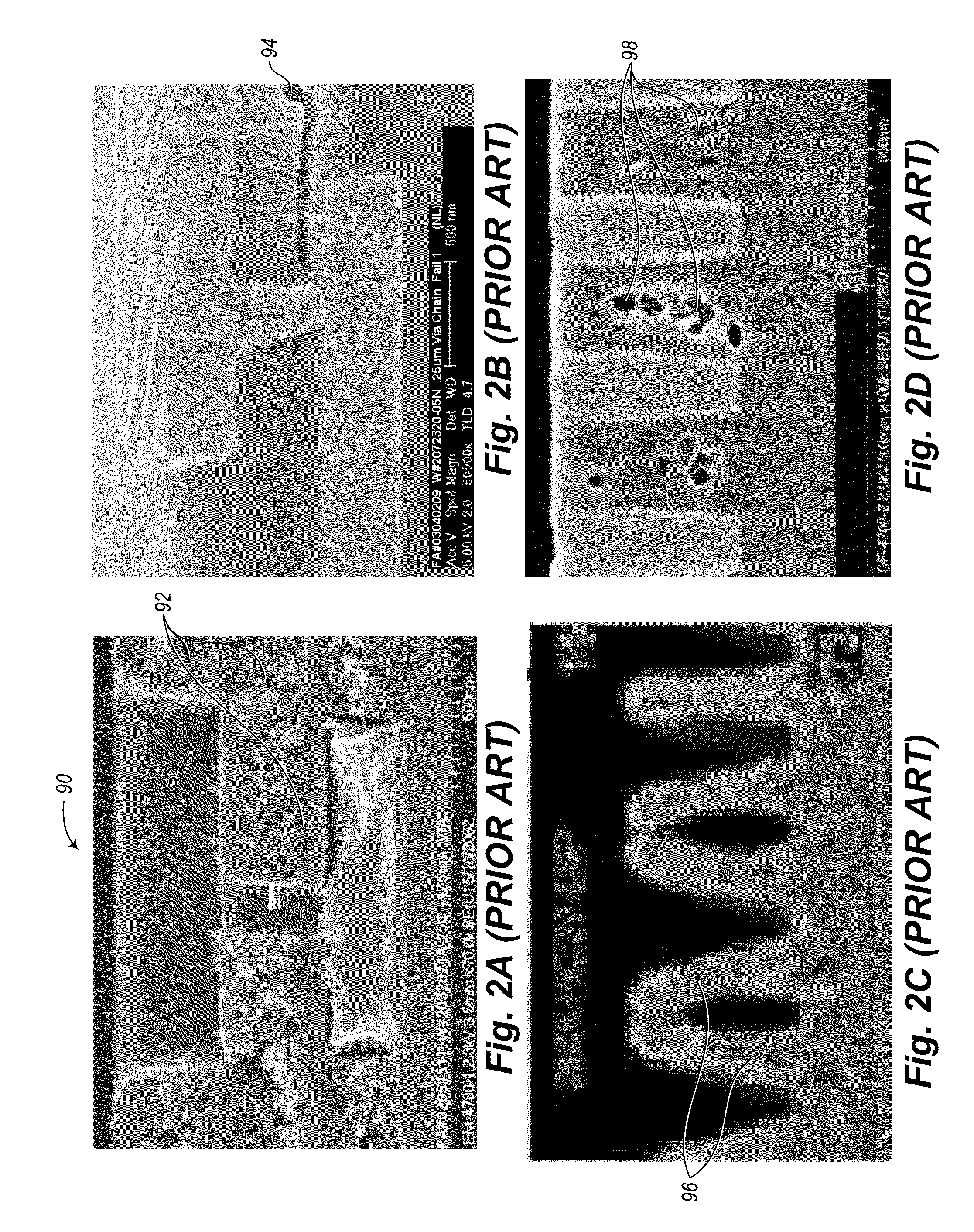
Consequently, mechanical properties such as the Young's modulus, cohesive strength, and adhesion of such porous films are degraded.
Another problem that tends to occur after etching ULK films is referred to as “dielectric flopover,” in which high aspect ratio structures 96 have been found to be unstable and tend to lean sideways as shown in FIG. 2C.
It is more difficult for metal deposition processes to fill high aspect ratio vias, which results in metal voids 98 as shown in FIG. 2D.
In summary, ULK dielectrics tend to be mechanically unstable, and are prone to have poor strength, poor adhesion, dielectric flopover, cracks, and voids.

Method used


Image

  • Trench interconnect having reduced fringe capacitance
  • Trench interconnect having reduced fringe capacitance
  • Trench interconnect having reduced fringe capacitance

Examples


Embodiment Construction

[0026]In the following description, certain specific details are set forth in order to provide a thorough understanding of various aspects of the disclosed subject matter. However, the disclosed subject matter may be practiced without these specific details. In some instances, well-known structures and methods of semiconductor processing comprising embodiments of the subject matter disclosed herein have not been described in detail to avoid obscuring the descriptions of other aspects of the present disclosure.

[0027]Unless the context requires otherwise, throughout the specification and claims that follow, the word “comprise” and variations thereof, such as “comprises” and “comprising” are to be construed in an open, inclusive sense, that is, as “including, but not limited to.”

[0028]Reference throughout the specification to “one embodiment” or “an embodiment” means that a particular feature, structure, or characteristic described in connection with the embodiment is included in at le...


PUM


Abstract

Ultra-low-k dielectric materials used as inter-layer dielectrics in high-performance integrated circuits are prone to be structurally unstable. The Young's modulus of such materials is decreased, resulting in porosity, poor film strength, cracking, and voids. An alternative dual damascene interconnect structure incorporates deep air gaps into a high modulus dielectric material to maintain structural stability while reducing capacitance between adjacent nanowires. Incorporation of a deep air gap having k=1.0 compensates for the use of a higher modulus film having a dielectric constant greater than the typical ultra-low-k (ULK) dielectric value of about 2.2. The higher modulus film containing the deep air gap is used as an insulator and a means of reducing fringe capacitance between adjacent metal lines. The dielectric layer between two adjacent metal lines thus forms a ULK / high-modulus dielectric bi-layer.

Description

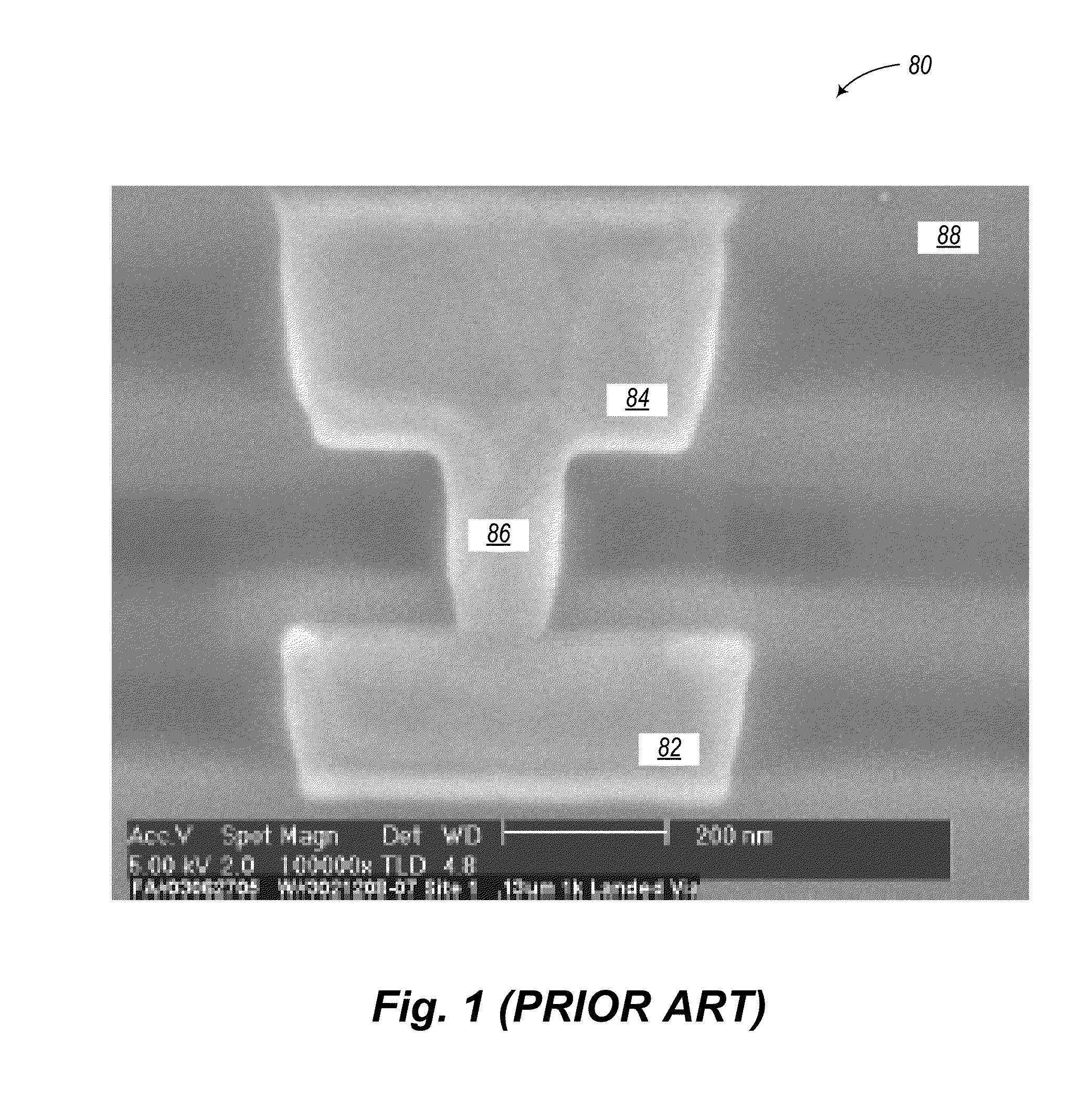
BACKGROUND[0001]1. Technical Field[0002]The present disclosure relates to the fabrication of nanowires for interconnecting integrated circuits and, in particular, to improvements in performance and reliability of inter-layer dielectrics used in a dual damascene process.[0003]2. Description of the Related Art[0004]There has been widespread use of damascene interconnect structures in microcircuit fabrication since the late 1990s when the semiconductor industry shifted from aluminum to copper metallization. A damascene interconnect process forms inlaid copper wiring by first etching trenches in a dielectric material, and then filling the trenches with copper, typically using a plating process such as, for example, electroplating. Through the use of a damascene process, semiconductor manufacturers can avoid etching copper. The term “dual damascene” refers to a process in which vertically adjacent metal lines and vias connecting them are formed in the same dielectric layer. FIG. 1 shows ...

Claims


Application Information

Patent Timeline
Patent Type & Authority Applications(United States)
IPC IPC(8): H01L23/528H01L23/522H01L23/532H01L21/768
CPCH01L23/528H01L21/76879H01L21/76807H01L2221/1094H01L23/5226H01L23/5222H01L23/53295H01L21/7682H01L23/5329H01L2924/0002H01L21/76831H01L2924/00
Inventor ZHANG, JOHN H.CHEN, HSUEH-CHUNGCLEVENGER, LAWRENCE A.MIGNOT, YANNRADENS, CARLWISE, RICHARD STEPHENLOQUET, YANNICKXU, YIHENG
Owner IBM CORP
Learn More