Beveled cell design for an alkaline battery to remove gas

Inactive Publication Date: 2015-06-11
ENCELL TECHNOLOGY LLC
View PDF14 Cites 2 Cited by
  • Summary
  • Abstract
  • Description
  • Claims
  • Application Information

AI Technical Summary

Benefits of technology

The patent text is discussing a design for an alkaline battery that results in improved capacity and performance. By beveling the cell casing, the battery is designed to apply more pressure to the electrode stack at the bottom while less pressure is applied at the top. This helps to prevent the electrodes from being pinched together and interfering with the battery's performance. The design also allows gas to escape from the battery without interfering with the battery's chemical reactions.

Problems solved by technology

Nickel hydroxide in the positive electrode, however, swells appreciably during charge and discharge, straining the support and restricting the choice of support type at the positive electrode.
These batteries however, do have disadvantages such as poor charge retention, poor low temperature performance, and low power density.
The large distance between electrodes which is enforced by the thick spacer has a negative impact on the power performance in the cell as the internal resistance of the cell increases with electrode spacing.
However, the construction of these cells is more expensive as the electrode design is not amenable to lower-cost manufacturing methods.
Furthermore, the large interelectrode spacing of these batteries imposed by the rigid support limits high rate performance as it increases electrolyte (ionic) resistance.
Such trapped gas can interfere with ionic transport and electrochemical reactions at the electrode surface and adversely affect battery performance.
Both electrodes are thermodynamically unstable in their charged state.
Ultimately, this leads to significant gas generation during charging and during self-discharge.
However, gas generation is a disadvantage in Ni—Fe batteries with small electrode spacing as in cells with polyolefin separators.
In this situation, the gas generated in the cell has a difficult time escaping and is trapped between the electrodes.
Such trapped gas can interfere with ionic transport and electrochemical reactions at electrode surfaces and adversely affect battery performance.

Method used


Image

  • Beveled cell design for an alkaline battery to remove gas
  • Beveled cell design for an alkaline battery to remove gas
  • Beveled cell design for an alkaline battery to remove gas

Examples


Embodiment Construction

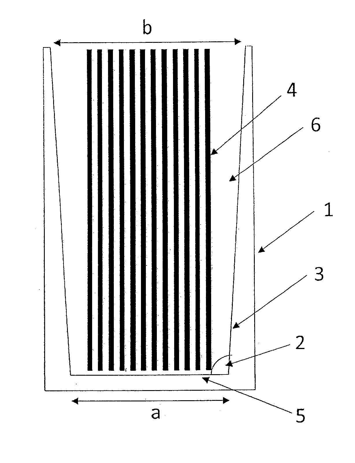
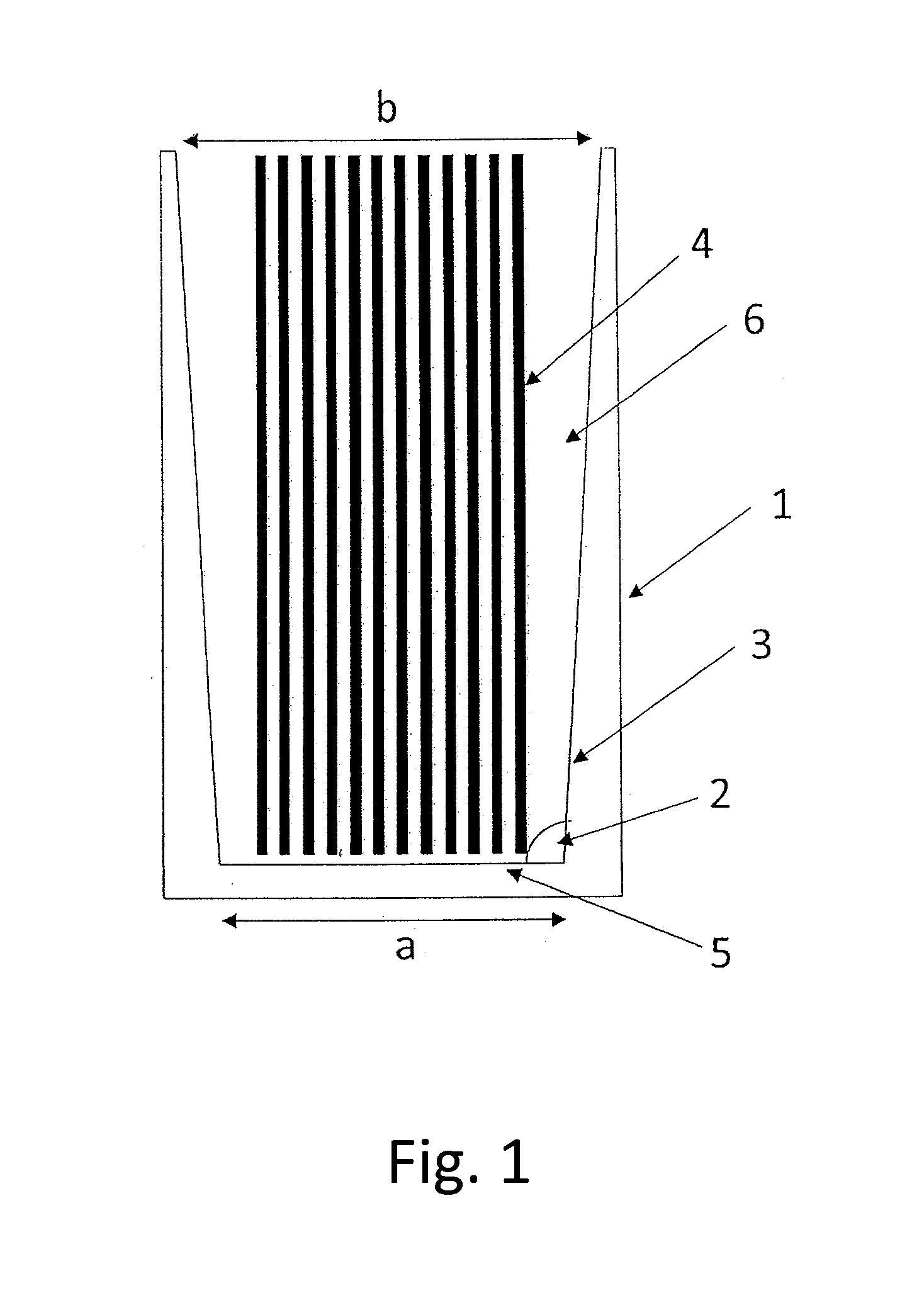
[0020]The present invention provides a cell design that allows gas to more easily escape from between the electrodes in an alkaline battery, e.g., a Ni—Fe or Zn—Mn battery, that uses separators, e.g., microporous separators. The invention provides a structure by which the advantages of higher charge and discharge rates and higher energy density may be achieved for alkaline batteries while reducing or avoiding trapped gases that interfere with electrochemical reactions at the electrode surface, which reactions degrade cell performance.

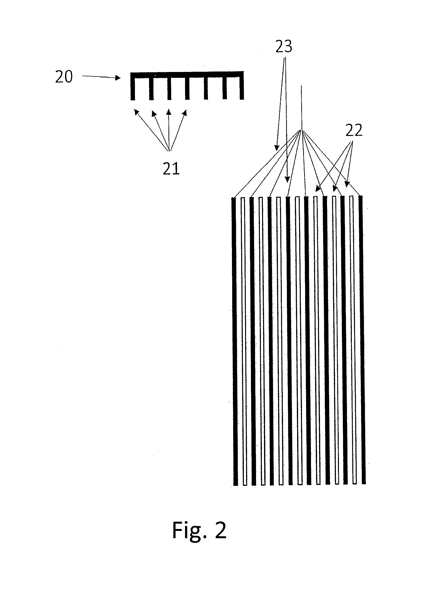
[0021]The cell design of the present invention creates a pressure gradient on the electrode stack that directs the gas out of the electrode stack. The pressure gradient is enforced on the electrode stack by the cell case design where some regions of the electrode stack are under greater pressure than other areas. Gas that forms between the electrodes flows from areas of high pressure to areas of lower pressure. The cell is designed so that the gradient ...


PUM


Abstract

Provided is an alkaline battery comprising an electrode stack having at least one positive electrode and at least one negative electrode with a separator disposed therebetween and a spacer between the tabs of similarly polarized electrodes of the electrode stack, which battery is contained in a cell casing that applies greater pressure to the electrode towards the bottom of the electrode stack and less pressure towards the top of the electrode stack. In one embodiment, the spacers between the tabs of similarly polarized electrodes are the teeth of a comb structure.

Description

RELATED APPLICATIONS [0001]The present application claims priority to U.S. provisional application 61 / 914,108, filed Dec. 10, 2013, and U.S. provisional application 61 / 914,036, filed Dec. 10, 2013, the contents of which applications are herein incorporated by reference in their entirety.FIELD OF INVENTION[0002]The present invention is in the technical field of energy storage devices. More particularly, the present invention is in the technical field of rechargeable batteries using an alkaline electrolyte, and having a particular cell design.STATE OF THE ART [0003]Batteries with an alkaline electrolyte have been known for over a hundred years. Most of these batteries are based on the use of a nickel oxide active material as the cathode paired with a various metals or metal-hydrides as the anode. A number of types of cell construction are possible for each of these batteries. These variations in cell construction lie mostly in the nature of electrode support utilized. For the positive...

Claims


Application Information

Patent Timeline
IPC IPC(8): H01M2/02H01M10/28H01M2/16H01M4/80H01M4/24H01M4/62H01M4/66H01M10/26H01M2/18H01M50/417H01M50/474H01M50/477
CPCH01M2/02H01M10/26H01M10/281H01M2/1653H01M2/18H01M4/808H01M4/244H01M4/24H01M4/622H01M4/661H01M4/248H01M4/62Y02E60/10Y02P70/50H01M50/417H01M50/477H01M50/474
Inventor OGG, RANDY GENEMEESE, MICHAELBENNETT, PHILSMITH, KEITH BRYANRODERS, MICHAELMARTIN, ELIZABETH
Owner ENCELL TECHNOLOGY LLC
Why Eureka
Try Eureka