Airborne Data Collection

a technology for airborne data and meters, applied in the field of reading utility meters, can solve the problems of high labor and time consumption of the reading system of meters, high cost, and many meters not being read as frequently, and achieve the effect of maximum ground coverag

Active Publication Date: 2015-06-11
DATAFLYTE PARTNERS LLC
View PDF33 Cites 22 Cited by
  • Summary
  • Abstract
  • Description
  • Claims
  • Application Information

AI Technical Summary

Benefits of technology

[0032]The system 804 includes an arrangement 200 of more than one antenna 202 (as depicted in FIGS. 2 and 3). In some embodiments the antennas 202 are disposed at a variety of angles in relation to each other and to a horizon and terrain 702 that is below the airborne platform 802 during data collection. In some embodiments the arrangement 200 is disposed within a belly pod or some other type of enclosure that is mounted to the platform 802, to shield the arrangement 200 from wind, weather, and other hazards. In other embodiments, the arrangement 200 is disposed within the platform 802. In one embodiment, flat panel or patch antennas 202 similar to ARC Solutions Model ARC-PA0913B01 are used. The high gain (12 dBi) and polarization allow the arrangement 200 of antennas 202 to be mounted in an optimized orientation from a higher altitude allowing for maximum ground coverage.

Problems solved by technology

Obviously, this system of reading meters is both labor and time intensive, and therefore costly.
Because of the effort and time required, many meters do not get read as frequently as would be desired by the utility company.
However, for a variety of reasons, the meter reader often has to spend some amount of time trying to find a position at which the two transceivers can reliably communicate.
Putting a transceiver on a mobile platform, such as a truck or an airplane, allows some of the meters to be read more quickly, but tends to completely miss a large number of the meters on a given route, because the mobile platform is not properly positioned to read those meters.

Method used


Image

  • Airborne Data Collection
  • Airborne Data Collection
  • Airborne Data Collection

Examples


Embodiment Construction

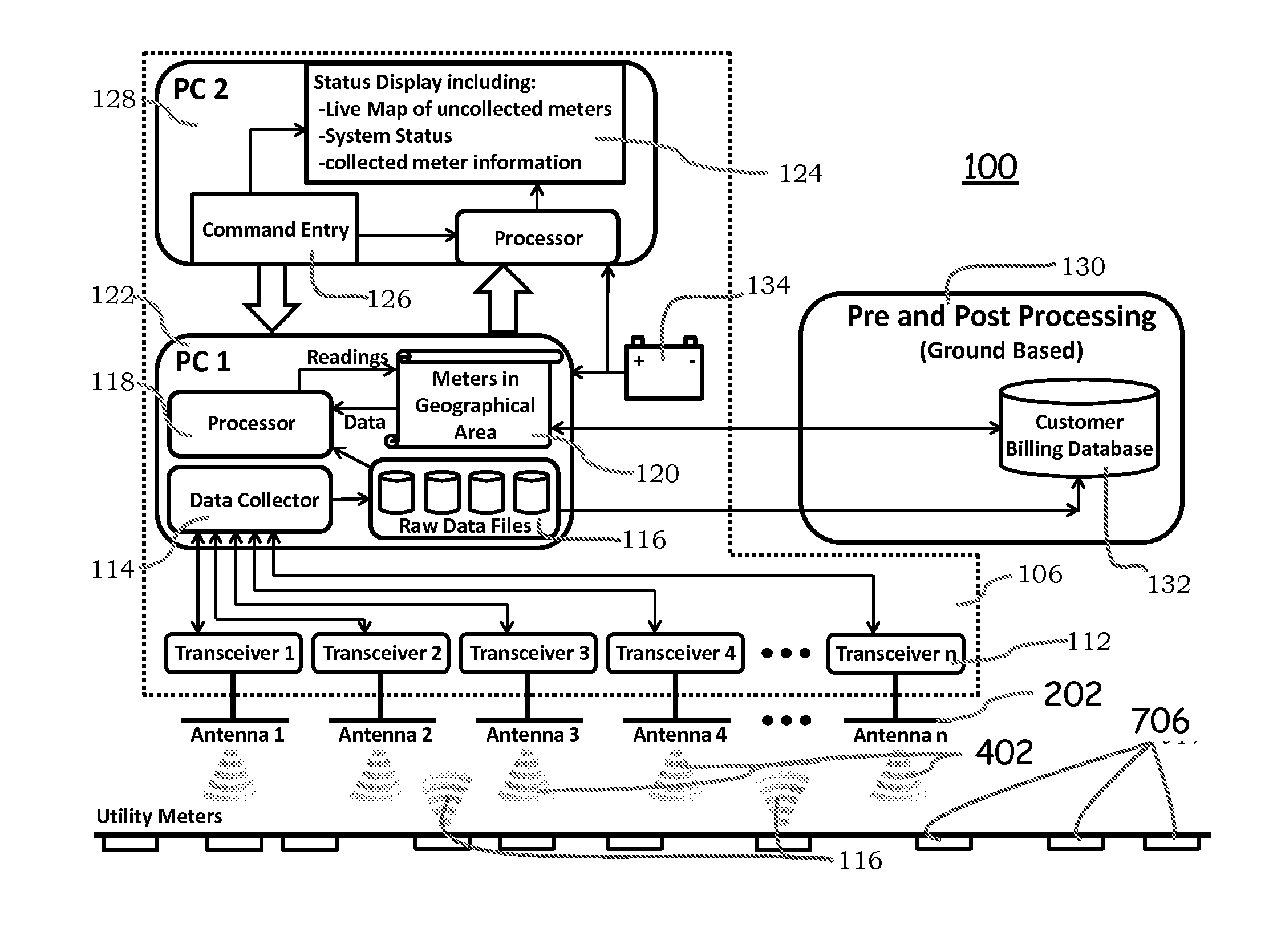
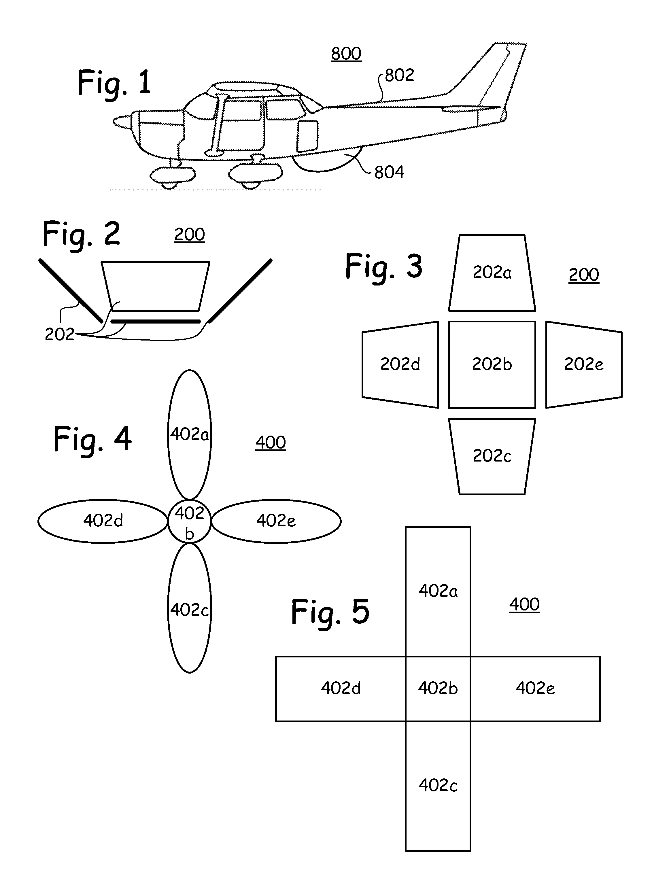
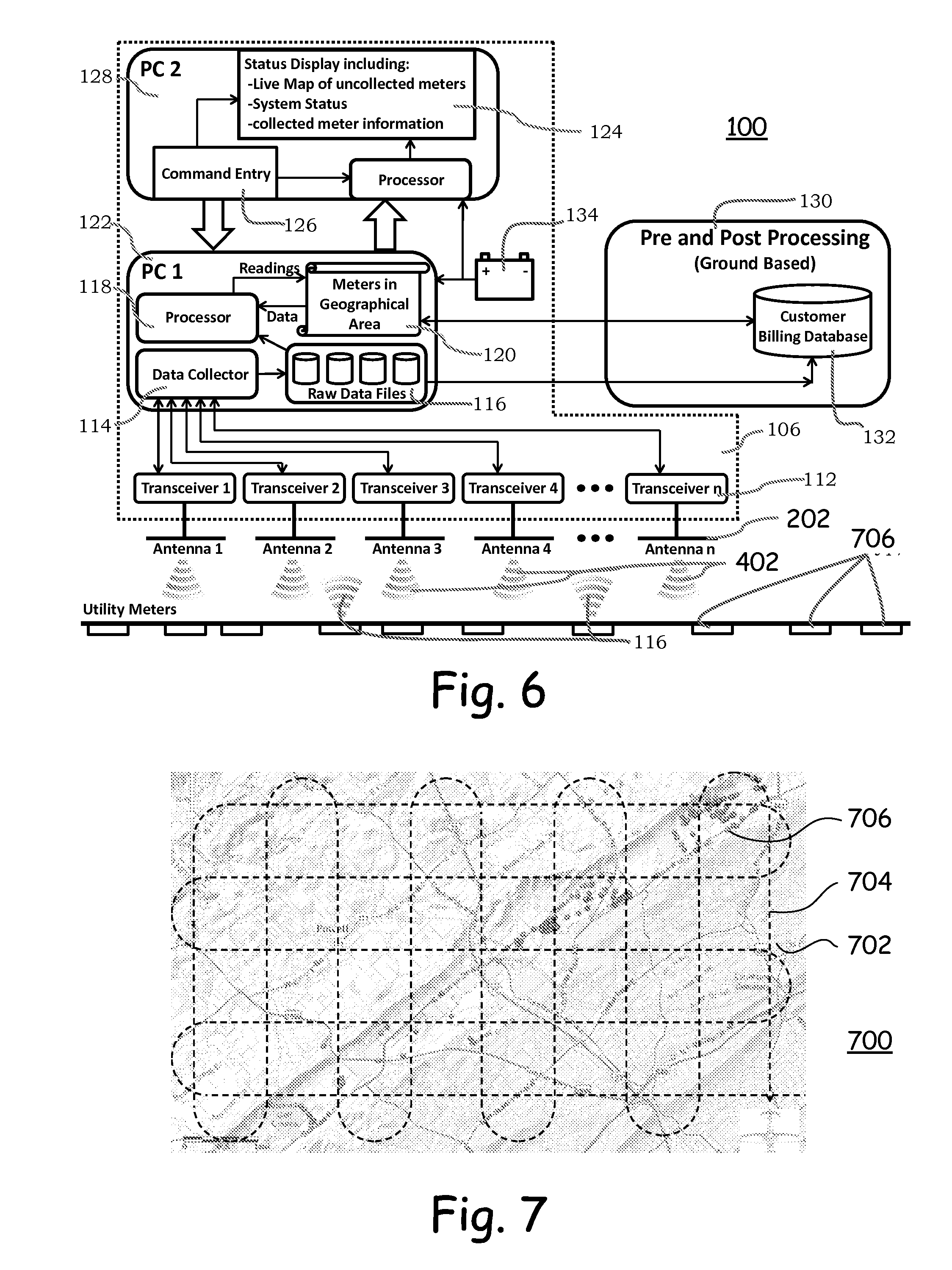
[0029]With reference now to FIG. 1, there is depicted a basic embodiment 800 of a meter data collection system 804 and an airborne platform 802. The platform 802 is a platform that is not continuously physically terrestrially tethered or depending, such as an airplane, glider, projectile, helicopter, drone, balloon, dirigible, satellite, or other such. The platform 802 in some embodiments is piloted from within the platform 802, and in other embodiments is remotely piloted. Piloting of the platform 802 is by human operator in some embodiments, and computer controlled in other embodiments. In some embodiments the airborne platform 802 collects meter data at an altitude of up to about five thousand feet. In one embodiment, the altitude is about one thousand feet, and provides ground coverage of about three thousand feet. During meter data collection, the platform 802 travels at a speed of up to about two hundred miles per hour, in some embodiments.

[0030]In operation, and with referenc...


PUM


Abstract

A meter reading system for communicating with Automated Meter Reading meters. The system includes an airborne platform and a meter data collection system disposed on the airborne platform. The meter data collection system includes antennas, with each of the antennas pointing in a different direction, one from another, and each antenna generally pointing downward when the airborne platform is airborne. The antennas receive meter data from the meters. The meter data collection system also includes transceivers, one each of the transceivers associated with and in signal communication with one each of the antennas. The transceivers receive the meter data through the antennas. A first computer is in signal communication with the transceivers, and receives the meter data from the transceivers.

Description

FIELD[0001]This applications claims rights and priority on prior pending U.S. provisional patent applications Ser. Nos. 61 / 913,685 filed Dec. 9, 2013 and 61 / 925,137 filed Jan. 8, 2014, the entire disclosures of which are incorporated herein by reference. This invention relates to the field of reading utility meters. More particularly, this invention relates to reading utility meters from an airborne platform.INTRODUCTION[0002]Utility meters are typically read by crews of meters readers who each have a route that they are responsible for. The meter reader walks up to each individual meter, identifies the meter on a list of meters, visually reads the dials on the meter, enters the value into a meter log, and then proceeds to the next meter on the route. At the end of the day, the collected data is transcribed into a database. This same routine must be performed for each meter in service by the utility company on a regular basis, when service is started or stopped, or when utility thef...

Claims


Application Information

Patent Timeline
Patent Type & Authority Applications(United States)
IPC IPC(8): H04W84/18G01R21/00
CPCG01R21/00H04W84/18G01D4/006G01R22/063H04W4/70Y02B90/20Y04S20/30
Inventor BAUER, MARTIN L.NOWER, DANIEL L.DISCHNER, JOHN M.MORSE, DANIEL J.
Owner DATAFLYTE PARTNERS LLC
Why Eureka
Try Eureka