Electrical connector

a technology of electrical connectors and connectors, which is applied in the direction of printed circuit stress/warp reduction, electrical apparatus contruction details, and association of printed circuit non-printed electric components, etc. it can solve the problems of affecting the electrical connection between the chip module and the circuit board, and the need for it has been unaddressed in the art. , to achieve the effect of stable electrical connection, low melting point and good elasticity

Active Publication Date: 2015-06-11
LOTES
View PDF8 Cites 6 Cited by
  • Summary
  • Abstract
  • Description
  • Claims
  • Application Information

AI Technical Summary

Benefits of technology

[0019]As compared with the related art, in certain embodiments of the present invention, the low melting point liquid metal is disposed on the surface of the elastic insulator. The continuous conducting path is formed between the first electronic element and the second electronic element through the liquid metal. It is ensured that the conductor has good elasticity, and further, the phenomenon that the conducting path is disconnected due to being pressed by the chip module may be avoided, so as to ensure the stable electrical connection between the chip module and the circuit board. Moreover, electrical transmission is performed by the use of the liquid metal, the impedance of the liquid metal is small, which can effectively reduce the impedance of the electrical connector, so as to ensure normal current transmission, and provide a clear and stable communication effect.

Problems solved by technology

The foregoing metal layer made of copper, nickel or gold is hard, and when the conductor is pressed by the chip module, a crack is extremely easily generated on the metal layer, resulting in disconnection of the electrical path on the surface of the elastomer, and affecting the electrical connection between the chip module and the circuit board.
Therefore, a heretofore unaddressed need exists in the art to address the aforementioned deficiencies and inadequacies.

Method used


Image

  • Electrical connector
  • Electrical connector
  • Electrical connector

Examples


second embodiment

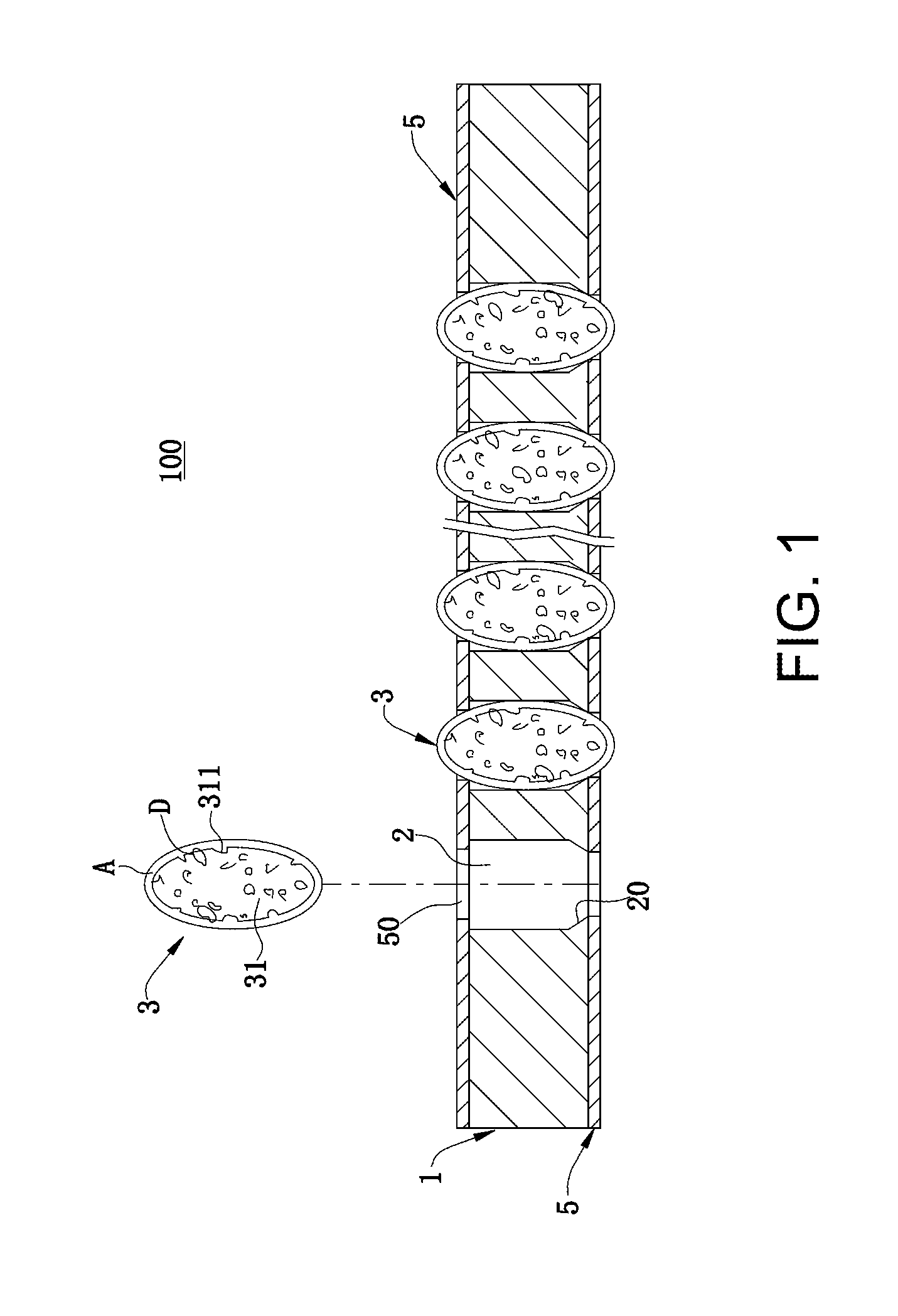
[0036]FIG. 5 and FIG. 6 show the present invention. An electrical connector 100 includes an insulating body 1 provided with multiple accommodating holes 2. A conductor 3 is accommodated in each of the accommodating holes 2. The conductor 3 includes multiple elastic insulators 31. Low melting point liquid metal A is arranged on a surface of each of the elastic insulators 31, and liquid metal A on outer surfaces of all the elastic insulators 31 in the same conductor 3 is in communication with each other. Specifically, each of the accommodating holes 2 is internally provided with a certain quantity of liquid metal A, and the liquid metal A is filled with multiple silicon rubber particles which are tiny and have good elasticity. By use of cheap silicon rubber particles as fillers, the quantity of the liquid metal A used may be reduced, so as to effectively reduce the cost. Moreover, by use of surfaces of multiple tiny silicon rubber particles, the liquid metal A may be effectively adsor...

first embodiment

[0038]In this embodiment, the liquid metal A may be made of a material basically the same as that in the Specifically, the bottom of the insulating body 1 may be firstly provided with a covering layer 5. Next, multiple tiny silicon rubber particles are placed in the accommodating hole 2. Then the liquid metal A is placed in the accommodating hole 2, so that the liquid metal A fills the entire accommodating hole 2. Finally the top of the insulating body 1 is provided with another covering layer 5.

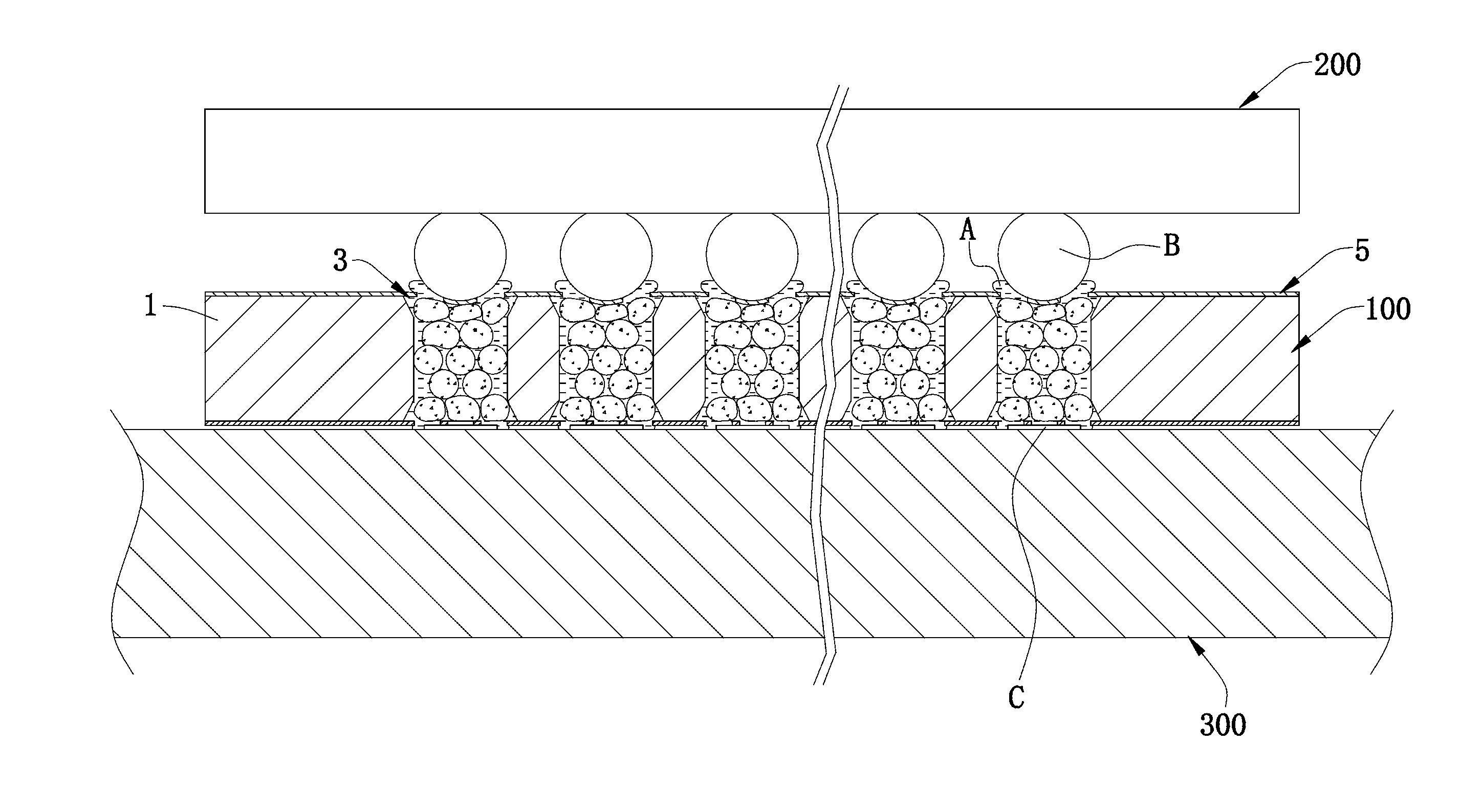
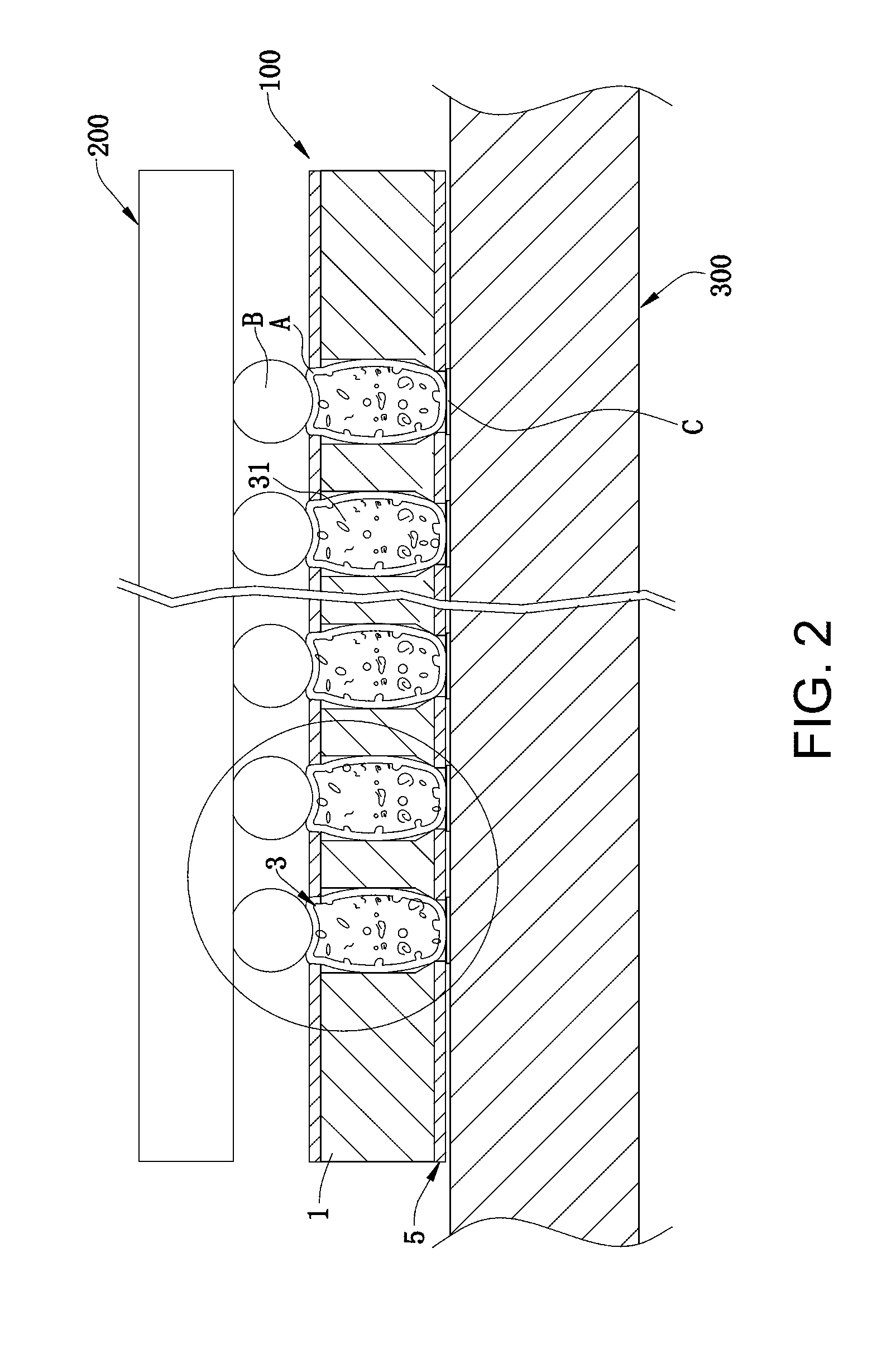
[0039]As shown in FIG. 6, when the chip module 200 is pressed on the electrical connector 100, the covering layers 5 on the upper and lower surfaces of the insulating body 1 may both be elastically deformed, and the silicon rubber particles in the accommodating hole 2 are also extruded and deformed. In this case, the liquid metal A in the accommodating hole 2 is extruded, so a small part of the liquid metal A in the accommodating hole 2 is exposed out of the perforation 50 of the covering l...


PUM


Abstract

An electrical connector for electrically connecting a first electronic element to a second electronic element includes an insulating body and multiple conductors. The insulating body has multiple accommodating holes. Each conductor is accommodated in a corresponding accommodating hole. Each conductor has an elastic insulator and low melting point liquid metal wrapping a surface of the elastic insulator, such that a continuous conducting path is formed by the liquid metal between the first electronic element and the second electronic element.

Description

CROSS-REFERENCE TO RELATED APPLICATION[0001]This non-provisional application claims priority under 35 U.S.C. §119(a) on Patent Application No. 201320791167.5 filed in P.R. China on Dec. 5, 2013, the entire contents of which are hereby incorporated by reference.[0002]Some references, if any, which may include patents, patent applications and various publications, may be cited and discussed in the description of this invention. The citation and / or discussion of such references, if any, is provided merely to clarify the description of the present invention and is not an admission that any such reference is “prior art” to the invention described herein. All references listed, cited and / or discussed in this specification are incorporated herein by reference in their entireties and to the same extent as if each reference was individually incorporated by reference.FIELD OF THE INVENTION[0003]The present invention relates generally to an electrical connector, and more particularly to an ele...

Claims


Application Information

Patent Timeline
Patent Type & Authority Applications(United States)
IPC IPC(8): H05K1/02H05K1/11H05K1/18H05K1/09
CPCH05K1/0271H05K1/09H05K2201/10954H05K1/181H05K1/115
Inventor JU, TED
Owner LOTES
Why Eureka
Try Eureka