
Heat dissipating fin and heat dissipating device

Inactive Publication Date: 2015-06-18
ASUSTEK COMPUTER INC
View PDF3 Cites 4 Cited by
  • Summary
  • Abstract
  • Description
  • Claims
  • Application Information

AI Technical Summary

Benefits of technology

The invention provides a heat dissipating fin and device that can evenly hold a pipe and reduce damage during assembly. This improves heat dissipation efficiency.

Problems solved by technology

However, the wear at the connection between the pipe and the fins is not easily avoided via the single-direction stamping, even the micro-structure of the pipe is destroyed, and thus the quality of the heat dissipating device is poor.
Additionally, since the wear at the front end (which is stamped first) is more serious, and the holding force between the heat dissipating fin and the worn portion of the pipe is decreased, the holding force between the heat dissipating fin and the pipe is not uniform, and the stability of the whole architecture is affected.

Method used


Image

  • Heat dissipating fin and heat dissipating device
  • Heat dissipating fin and heat dissipating device
  • Heat dissipating fin and heat dissipating device

Examples


Embodiment Construction

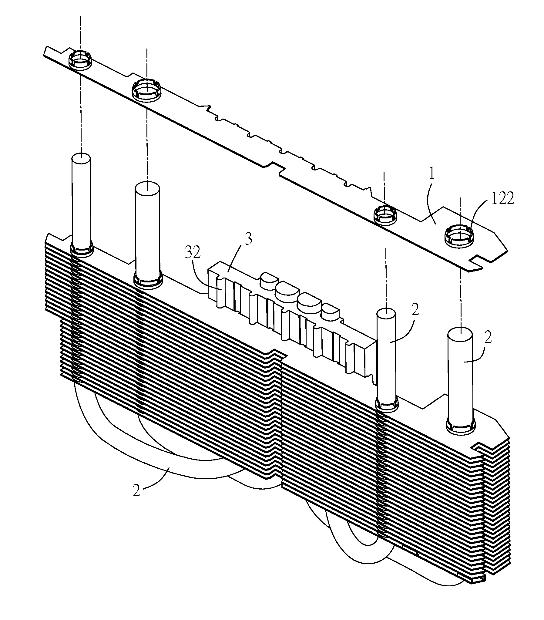
[0020]A heat dissipating fin and a heat dissipating device will be illustrated with relating drawings, and the same number donates the same component.

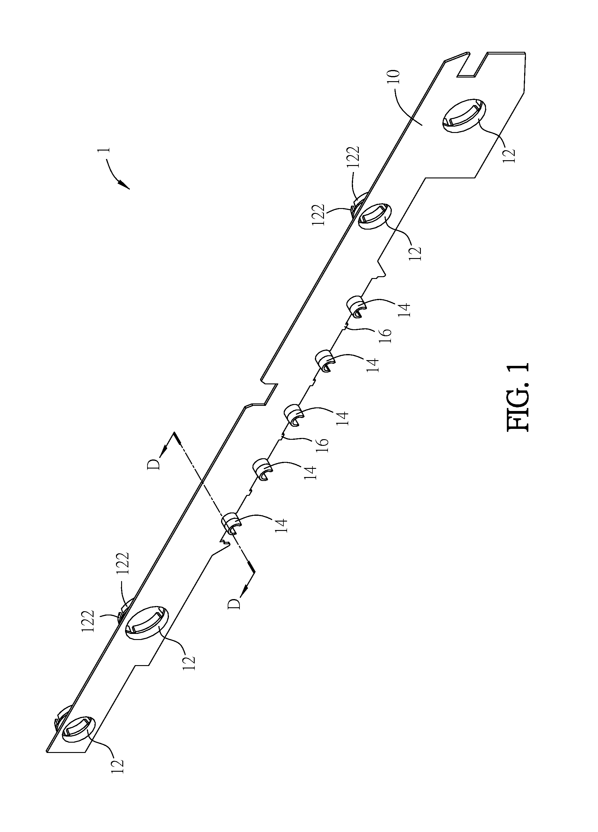
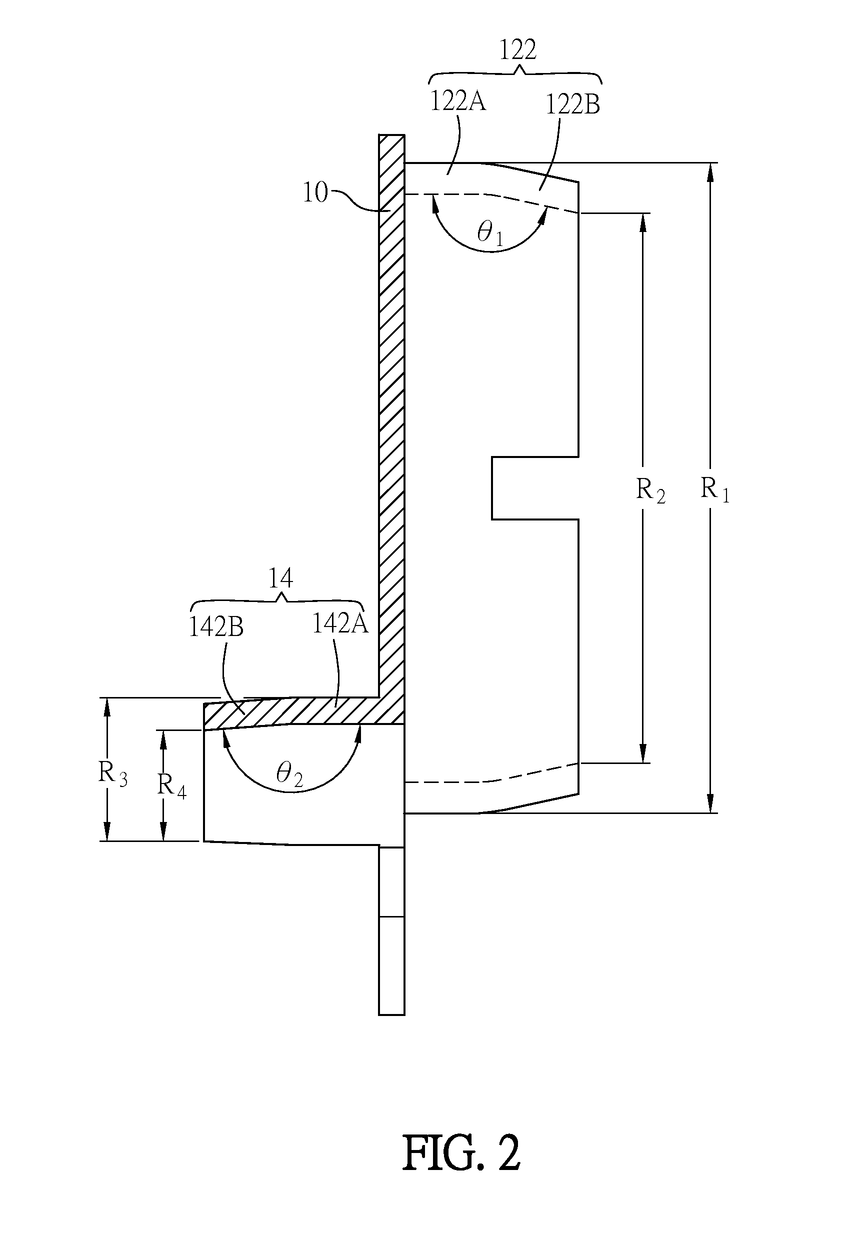
[0021]FIG. 1 is a schematic diagram showing a heat dissipating fin in an embodiment of the disclosure. FIG. 2 is a schematic diagram showing a cross section of the heat dissipating fin in FIG. 1 along the cross line DD. FIG. 3 is an enlarged view showing a through hole of the heat dissipating fin in FIG. 1.

[0022]In an embodiment, a heat dissipating fin 1 includes a main body 10 and at least a through hole 12 formed on the main body 10. In the embodiment, the number of the through hole 12 is four, however, the number of the through hole 12 is not a limitation herein. In an embodiment, the material of the heat dissipating fin 1 is aluminum, copper, aluminum alloy, copper alloy or copper aluminum alloy which is not limited herein.

[0023]Each through hole 12 at least includes two collar portions 122, each collar portion 122 forms on the edg...


PUM


Abstract

A heat dissipating fin including a main body and a through hole is provided. The through hole is formed at the main body. The through hole includes at least two collar portions, and the collar portions are formed on an edge of the through hole. Each of the collar portions includes a first extending portion and a first bridging portion. A first angle is formed between the first extending portion and the first bridging portion. The heat dissipating fin and the heat dissipating device can form a uniform holding force between the heat dissipating fin and the pipe, reduce the damage of the pipe in the assembly, and improve the heat dissipation efficiency.

Description

CROSS-REFERENCE TO RELATED APPLICATION[0001]This application claims the priority benefit of TW application serial No. 102146943, filed on Dec. 18, 2013. The entirety of the above-mentioned patent application is hereby incorporated by references herein and made a part of specification.BACKGROUND OF THE INVENTION[0002]1. Field of the Invention[0003]The invention relates to a heat dissipating fin and, more particularly, to a heat dissipating fin applied to a heat dissipating device.[0004]2. Description of the Related Art[0005]Heat is generated when an electronic device operates. To avoid that too much heat are accumulated at the electronic device and affects the performance of the electronic device, a heat dissipating unit is usually applied to the electronic device.[0006]A conventional heat dissipating device at least includes a base plate contacted to a heat source, multiple fins and a pipe connected to the base plate and passing through the fins, the heat generated from the electron...

Claims


Application Information

Patent Timeline
IPC IPC(8): F28F3/08
CPCF28F3/086F28D15/0233F28D15/0275F28F1/32H01L21/4882H01L23/3672H01L23/427H01L23/467H01L2924/0002H01L2924/00
Inventor HUANG, YUNG-CHING
Owner ASUSTEK COMPUTER INC
Learn More