
Multifunction imager

a multi-functional, imager technology, applied in the field of multi-functional imagers, can solve the problems of limiting measurement accuracy, insufficient speed of instruments to image moving targets or stationary targets from moving platforms, and substantial processing time required

Active Publication Date: 2015-06-18
RAYTHEON CO
View PDF11 Cites 35 Cited by
  • Summary
  • Abstract
  • Description
  • Claims
  • Application Information

AI Technical Summary

Benefits of technology

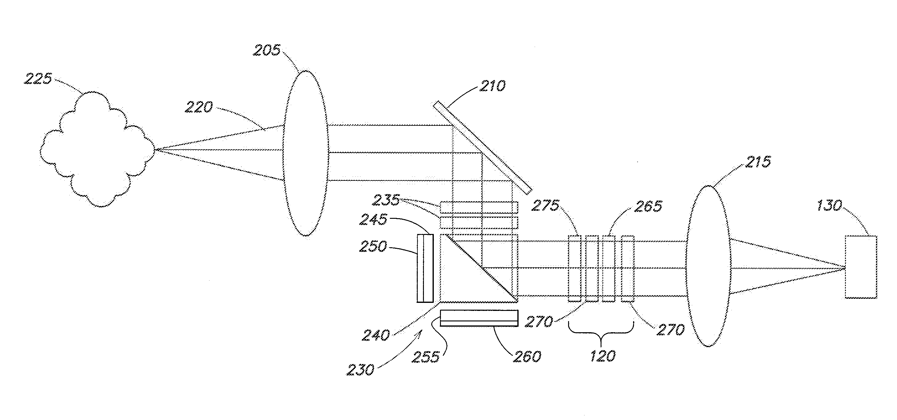
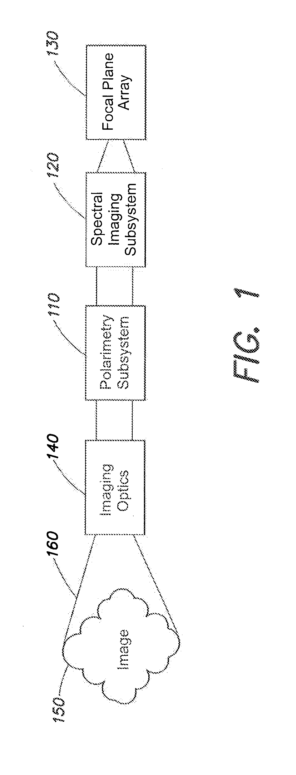
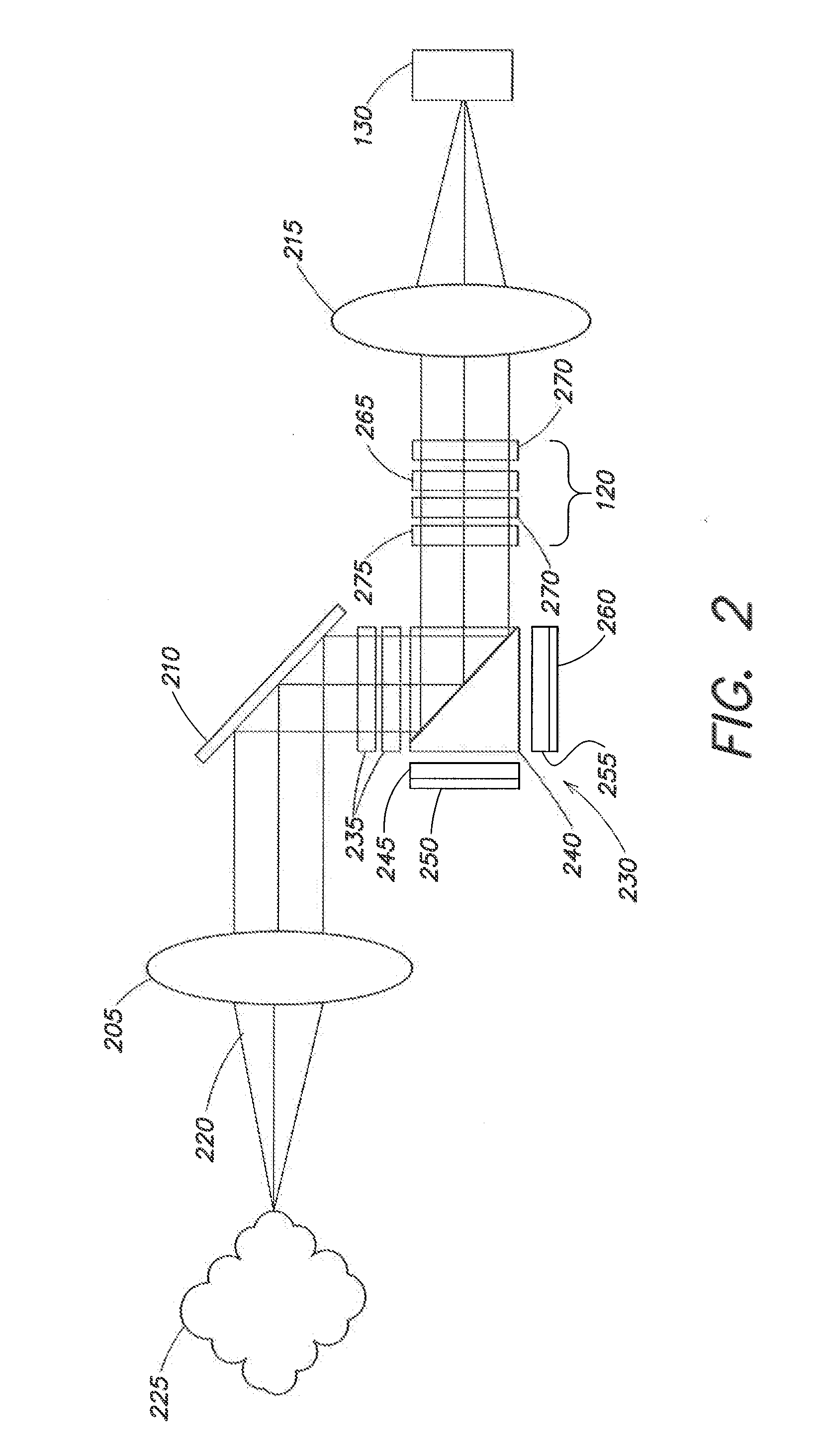
This patent describes a multifunction optical imaging system that can operate as a digital camera, an imaging polarometer, a spectral imager, and a polarimetric spectral imager. The system includes an imaging optical subsystem, a focal plane array, and a programmable polarimetry subsystem. The programmable polarimetry subsystem can switch between an ON state and an OFF state to provide different functions. The system also includes a spectral imaging subsystem that can switch between an ON state and an OFF state to provide different spectral imaging modes. The system can be controlled to turn off selected functionality and can electrically switch between different modes.

Problems solved by technology

Such instruments are not fast enough to image moving targets or stationary targets from moving platforms.
Although complete polarization information may be acquired from a single exposure of the detector array, the limited bandwidth of the spatial modulation used to recover the polarization information may limit measurement accuracy, and the processing time required is substantial.
In each case scanning limits the data acquisition speed such that only static images can be reasonably collected from static platforms.
Furthermore, image reconstitution suffers from incomplete sampling of the data cube that is inherent to the limited range of diffraction angles (the missing cone problem).

Method used


Image

  • Multifunction imager
  • Multifunction imager
  • Multifunction imager

Examples


Embodiment Construction

[0022]Although polarimetric and spectral imagers are known, conventional devices cannot be operated independently as polarimeters or spectral imagers, and nor can they be reduced to a camera mode for operation in low light situations. Additionally, when two or more instruments are used to provide the different functions, there are registration errors between images captured by the different instruments.

[0023]Aspects and embodiments are directed to implementing the polarizing components of a polarimeter and the dispersing elements of a spectral imager such that each function can be independently turned off, rendering the respective optical train a clear aperture. This arrangement enables cascading the polarimeter, spectral imager, and camera in a common optical train, and programmably selecting which of the functions is to be operative at any given time. With the ability to independently turn on and off the polarimetry and spectral dispersing functions with programmable components, t...


PUM

PropertyMeasurementUnit
applied voltagesaaaaaaaaaa
ellipticity angleaaaaaaaaaa
wavelength rangeaaaaaaaaaa

Abstract

A programmable multifunction spectral and / or polarization imager. In one example, such an imager includes an imaging optical subsystem configured to receive electromagnetic radiation from a distant scene, a focal plane array configured to produce an image of the scene, and a programmable polarimetry subsystem electrically switchable between an ON state in which the polarimetry subsystem receives the electromagnetic radiation and provides polarized electromagnetic radiation to the focal plane array, and an OFF state in which the polarimetry system is configured as a first substantially clear aperture that passes the electromagnetic radiation to the focal plane array. In certain examples, the imager includes a programmable spectral imaging sub-system configurable between an ON state and an OFF state.

Description

CROSS-REFERENCE TO RELATED APPLICATIONS[0001]This application claims priority to and the benefit of co-pending U.S. Provisional Application No. 61 / 915,652 titled “MULTIFUNCTION IMAGER” and filed on Dec. 13, 2013, which is herein incorporated by reference in its entirety for all purposes.BACKGROUND[0002]There are a variety of types of imagers or cameras. Conventional digital cameras capture the spatial distribution of intensity and color in a scene, usually using a detector that includes a two dimensional array of pixels, such as a focal plane array (FPA), for example.[0003]A “polarimetric imager” or “polarimeter” is a camera capable of viewing a scene in polarized light. The end result is detection and analysis of the polarization state of light reflected from an object, which is sensitive to the object orientation, composition, and surface roughness. Manmade objects tend to have highly polarized returns, whereas natural objects more often do not, and this has proven to be a useful ...

Claims


Application Information

Patent Timeline
Patent Type & Authority Applications(United States)
IPC IPC(8): G01J1/04G02F1/1347G01J3/02G01J1/42G01J3/28
CPCG01J1/0429G01J1/42G02F1/13473G01J3/0224G01J3/2823G01J3/18G01J4/04
Inventor DORSCHNER, TERRY
Owner RAYTHEON CO
Learn More