Liquid crystal display device

a liquid crystal display and display device technology, applied in static indicating devices, non-linear optics, instruments, etc., can solve the problems of excessive or deficient dac output in the direction of non-linear optics, excessive power consumption, etc., to reduce display quality, deficient dac capability, etc.

Inactive Publication Date: 2012-04-17
SHARP KK
View PDF17 Cites 0 Cited by
  • Summary
  • Abstract
  • Description
  • Claims
  • Application Information

AI Technical Summary

Benefits of technology

[0007]Accordingly, it is an object of the present invention to provide a liquid crystal display device, in which increased power consumption due to an excessive DAC capability and reduced display quality due to a deficient DAC capability do not occur as a result of dynamically adjusting the DAC capability such that variation in the characteristics of the liquid crystal panel is compensated.
[0009]The present invention permits implementation of a liquid crystal display device, in which increased power consumption due to an excessive DAC capability and reduced display quality due to a deficient DAC capability are prevented by dynamically adjusting the DAC capability so as to compensate for variation in the characteristics of liquid crystal panels.

Problems solved by technology

Accordingly, the problem with the conventional method, in which the determination of the DAC output capability was based on the results of simulation of the characteristic values of liquid crystal panels, was that the excessive or deficient DAC output in liquid crystal display devices provided with liquid crystal panels with characteristics deviating from the average values was not eliminated.

Method used


Image

  • Liquid crystal display device
  • Liquid crystal display device
  • Liquid crystal display device

Examples


Embodiment Construction

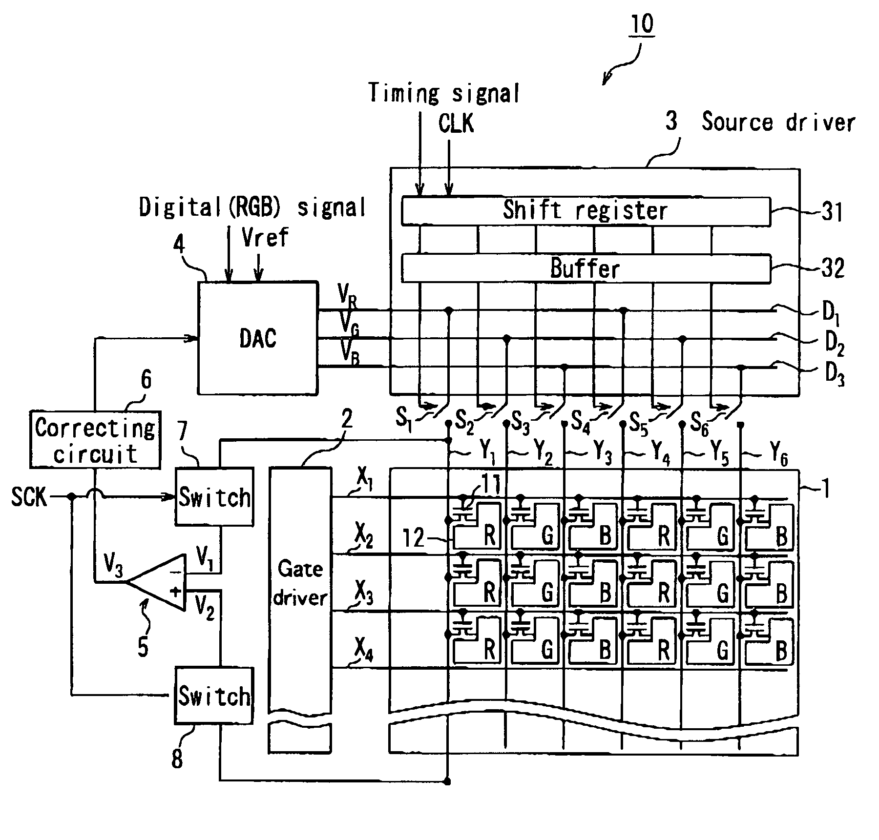
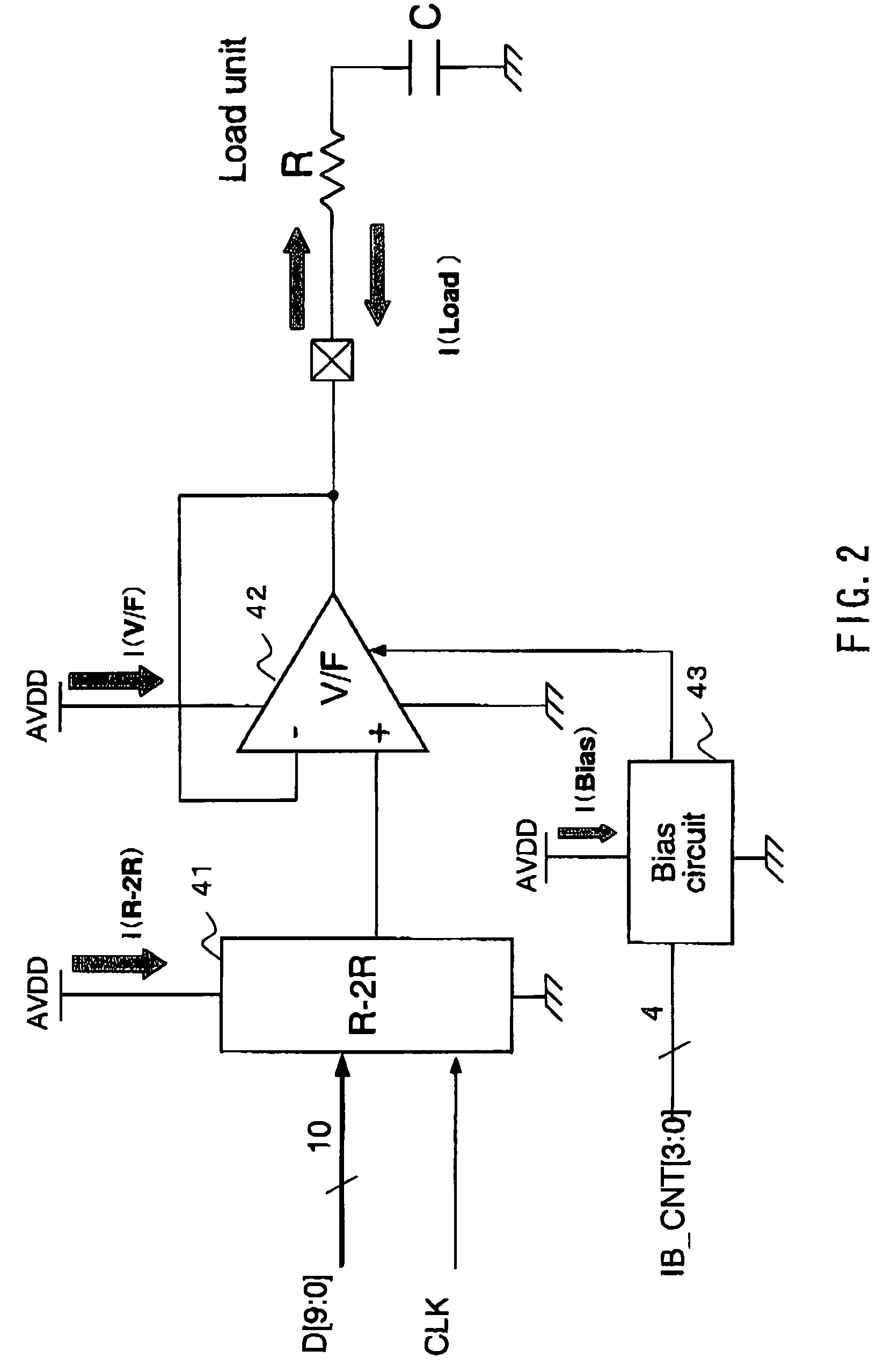
[0016]The liquid crystal display device of the present invention, which is a liquid crystal display device having liquid crystal sandwiched between a pair of substrates, includes: multiple signal lines arranged in a mutually parallel relationship on one of the substrates of the pair of substrates; a digital-to-analog converter circuit that converts data signals inputted as digital signals to analog signals; a signal line driver circuit that distributes and inputs the analog signals output from the digital-to-analog converter circuit to the multiple signal lines; a comparing circuit that compares a first voltage, which is the voltage of the analog signal detected on the input side of the signal lines, and a second voltage, which is the voltage of the analog signal detected on the side opposite the input side of the signal lines; and a correcting circuit that corrects the output of the digital-to-analog converter circuit based on the comparison results of the comparing circuit.

[0017]A...


PUM


Abstract

In one embodiment of the present application, a liquid crystal display device is disclosed, in which increased power consumption due to an excessive DAC capability and reduced display quality due to a deficient DAC capability do not occur as a result of dynamically adjusting the DAC capability such that variation in the characteristics of the liquid crystal panel is compensated. The liquid crystal display device comprises a digital-to-analog converter circuit that converts data signals inputted as digital signals to analog signals; a source driver that distributes and inputs analog signals output from the digital-to-analog converter circuit to a plurality of source lines Y; a differential amplifier that compares the voltage V1 detected on the input side of a source line Y and voltage V2 detected on the side opposite the input side of the source line Y; and a correcting circuit that corrects the output of the digital-to-analog converter circuit that corrects the output of the digital-to-analog converter circuit based on the comparison results of the differential amplifier.

Description

TECHNICAL FIELD[0001]The present invention relates to liquid crystal display devices and, in particular, relates to a liquid crystal display device displaying images by receiving a data signal as a digital signal input and supplying analog signals obtained by digital-to-analog conversion to source lines.BACKGROUND ART[0002]Liquid crystal display devices have been known in the past that comprise a digital signal input terminal and receive a data signal etc. used for displaying images as a digital input. In order to convert the input digital signal to analog signals, such liquid crystal display devices comprise a digital-to-analog converter circuit (DAC) located between the above-mentioned digital signal input terminal and source lines (signal lines) disposed in the columnwise direction of the liquid crystal panel. This DAC is sometimes incorporated into a signal line driver circuit (source driver) and sometimes provided outside of the source driver. The data signals output from the D...

Claims


Application Information

Patent Timeline
Patent Type & Authority Patents(United States)
IPC IPC(8): G09G3/36
CPCG09G3/2011G09G3/3648G09G3/3688G02F1/13306G09G2310/027G09G2320/0223G09G2320/0233G09G2320/043
Inventor NII, YUSUKE
Owner SHARP KK
Why Eureka
Try Eureka