Prosthetic mitral valve

a mitral valve and prosthesis technology, applied in the field of prosthetic mitral valves, can solve the problems of congestive heart failure, low cardiac output, shortness of breath,

Active Publication Date: 2015-06-25
TEL HASHOMER MEDICAL RES INFRASTRUCTURE & SERVICES
View PDF4 Cites 409 Cited by
  • Summary
  • Abstract
  • Description
  • Claims
  • Application Information

AI Technical Summary

Benefits of technology

[0018]According to some embodiments of the invention, said at least one native mitral valve leaflet prevents the flow of blood between itself and said valve frame, at least in the direction passing from the left ventricle to the left atrium.

Problems solved by technology

Mitral valve insufficiency leads to many complications including arrhythmia, atrial fibrillation, cardiac palpitations, chest pain, congestive heart failure, fainting, fatigue, low cardiac output, orthopnea, paroxysmal nocturnal dyspnea, pulmonary edema, shortness of breath, and sudden death.
A challenge to deployment of a prosthetic mitral valve, analogous to a prosthetic aortic valve, is retention of the prosthesis in place during ventricular systole.

Method used


Image

  • Prosthetic mitral valve
  • Prosthetic mitral valve
  • Prosthetic mitral valve

Examples


Embodiment Construction

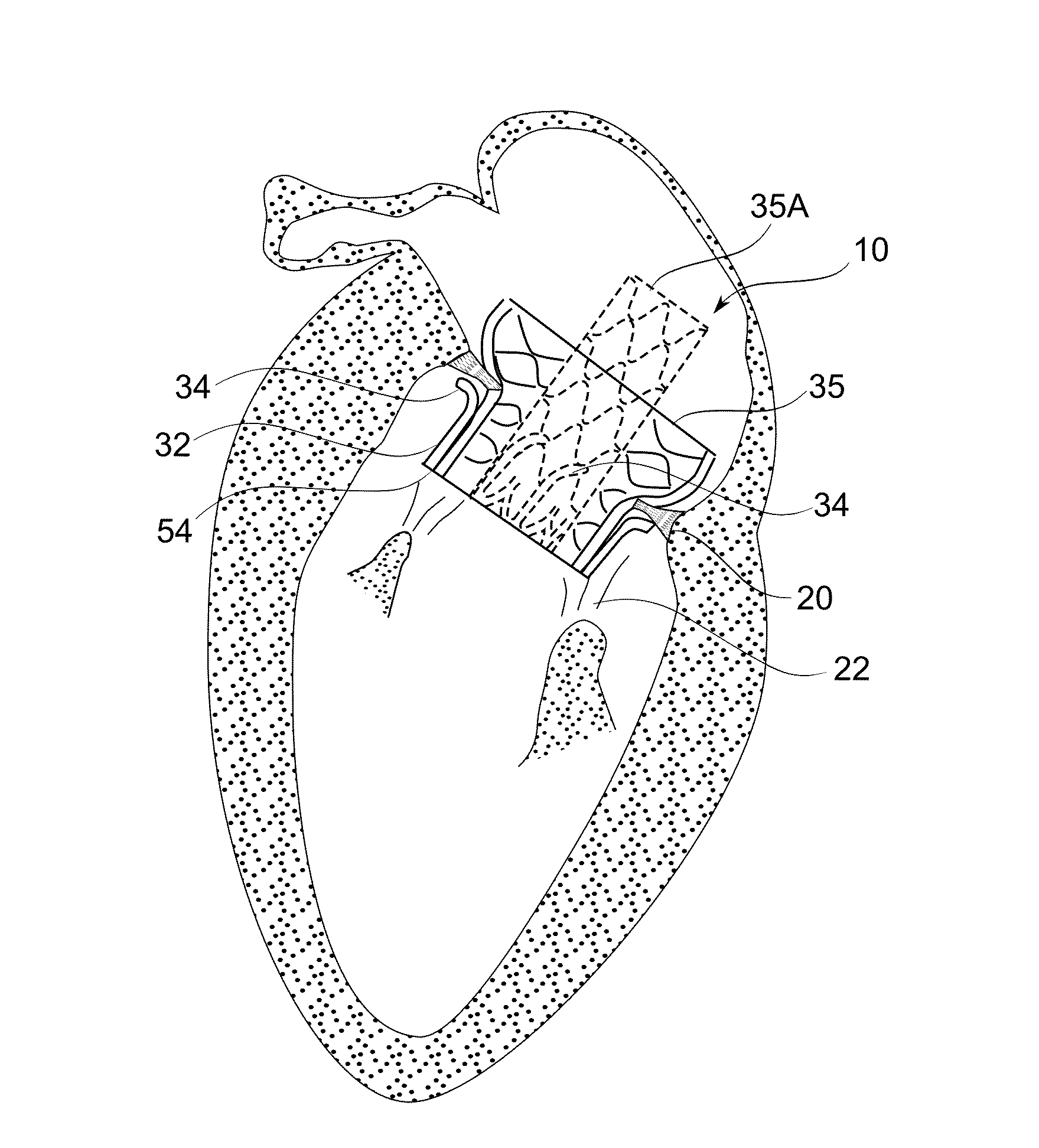
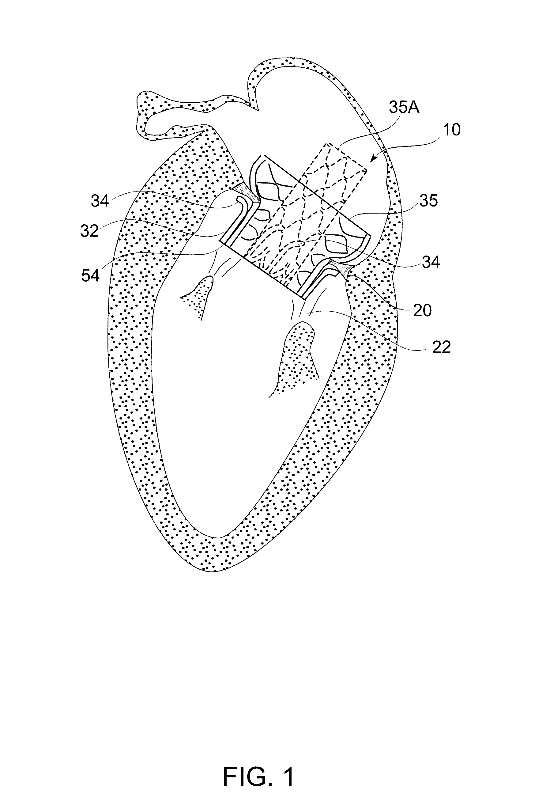
[0097]The present invention, in some embodiments thereof, relates to prosthetic heart valves, and in particular to prosthetic mitral valves. Some embodiments of the invention relate to methods and devices suitable for deploying prosthetic heart valves and in particular prosthetic mitral valves.

[0098]The principles, uses and implementations of the teachings of the invention may be better understood with reference to the accompanying description and figures. Upon perusal of the description and figures present herein, one skilled in the art is able to implement the teachings of the invention without undue effort or experimentation.

Overview

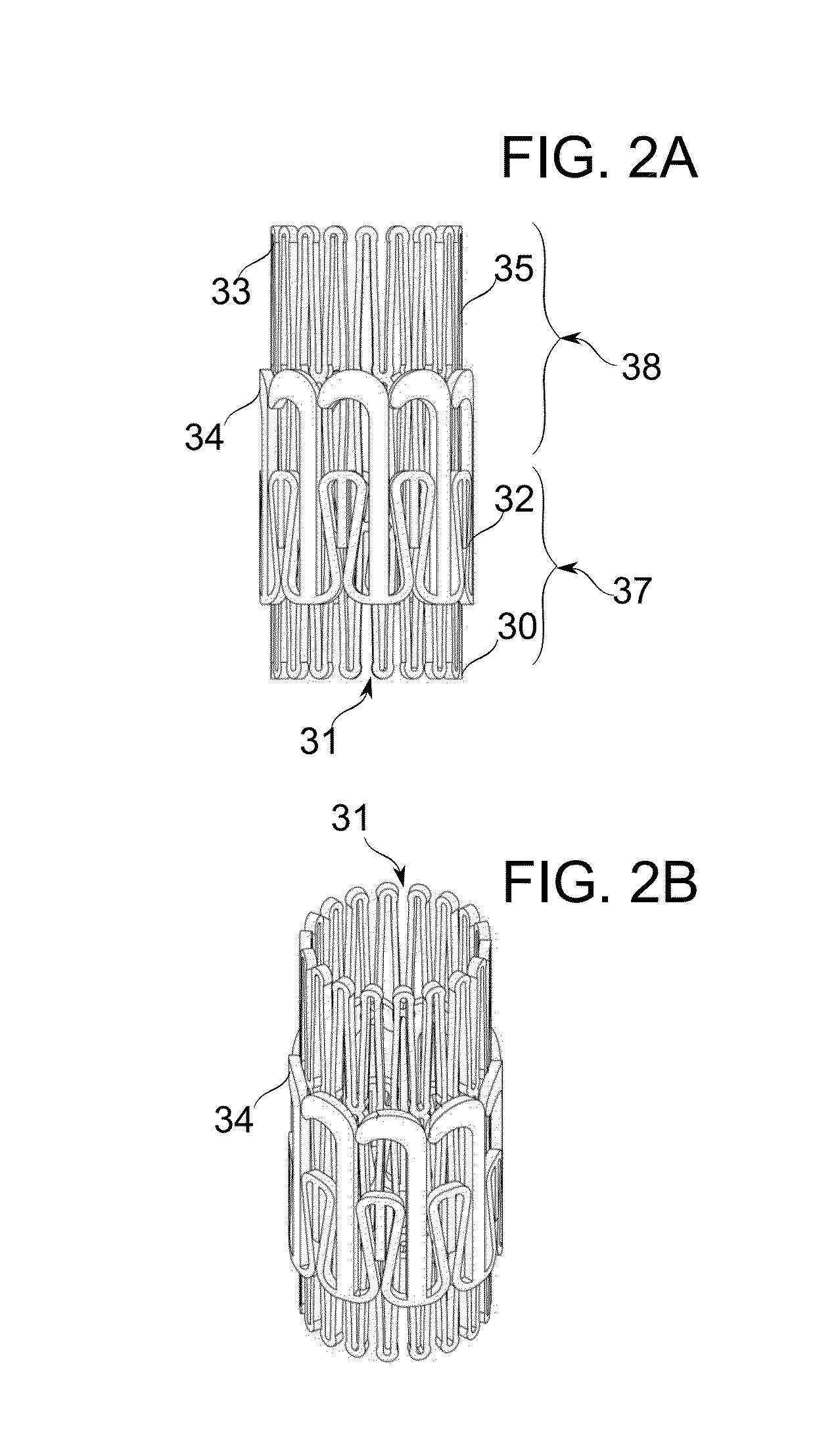
[0099]An aspect of some embodiments of the present invention relates to the fixation and functional deployment of a prosthetic mitral valve within a functioning heart using tension applied to the chords of the mitral valve to recruit native valve leaflets into the fixating mechanism and / or functional characteristics of the valve.

[0100]In some embodim...


PUM


Abstract

A prosthetic mitral valve with a frame comprises at least one arm shaped to deploy among a region of chordae tendineae of the native mitral valve to deflect these chords in order to pull the native valve leaflets around the frame to avoid paravalvular leaks. The frame may be made from two parts that are connected by sutures. The prosthetic valve may be deployed by a catherer comprising a deployment clamp attached to the valve frame where the deployment clamp is actuable to induce rotation of the frame.

Description

RELATED APPLICATION[0001]This application claims the benefit of priority under 35 USC §119(e) of U.S. Provisional Patent Application No. 61 / 649,319 filed May 20, 2012, the contents of which are incorporated herein by reference in their entirety.FIELD AND BACKGROUND OF THE INVENTION[0002]The present invention relates to the field of cardiac surgery, and more particularly to the field of prosthetic mitral valves.[0003]The human heart is a muscular organ that pumps deoxygenated blood through the lungs to oxygenate the blood and pumps oxygenated blood to the rest of the body by rhythmic contractions of four chambers.[0004]After having circulated in the body, deoxygenated blood from the body enters right atrium through the vena cava. The right atrium contracts, pumping the blood through a tricuspid valve into the right ventricle. The right ventricle contracts, pumping the blood through a pulmonary semi-lunar valve into the pulmonary artery which splits to two branches, one for each lung....

Claims


Application Information

Patent Timeline
Patent Type & Authority Applications(United States)
IPC IPC(8): A61F2/24
CPCA61F2/2418A61F2220/0016A61F2/243A61F2/2436A61F2/2457A61F2250/006A61F2230/0078A61F2230/005A61F2220/0058A61F2220/0075A61F2230/0013
Inventor RAANANI, EHUDORLOV, BORISHARARI, BOAZMEIRI, ODEDROZITSKY, LICHEN
Owner TEL HASHOMER MEDICAL RES INFRASTRUCTURE & SERVICES
Why Eureka
Try Eureka