Method for additive manufacturing

Active Publication Date: 2015-06-25
ARCAM AB
View PDF6 Cites 114 Cited by
  • Summary
  • Abstract
  • Description
  • Claims
  • Application Information

AI Technical Summary

Benefits of technology

[0009]There is a demand for additive manufacturing techniques which is capable of building three-dimensional articles with predicta

Problems solved by technology

No correction or compensation was made for long or short scan length, leading to vast differences in melt behavior of t

Method used


Image

  • Method for additive manufacturing
  • Method for additive manufacturing
  • Method for additive manufacturing

Examples


first example embodiment

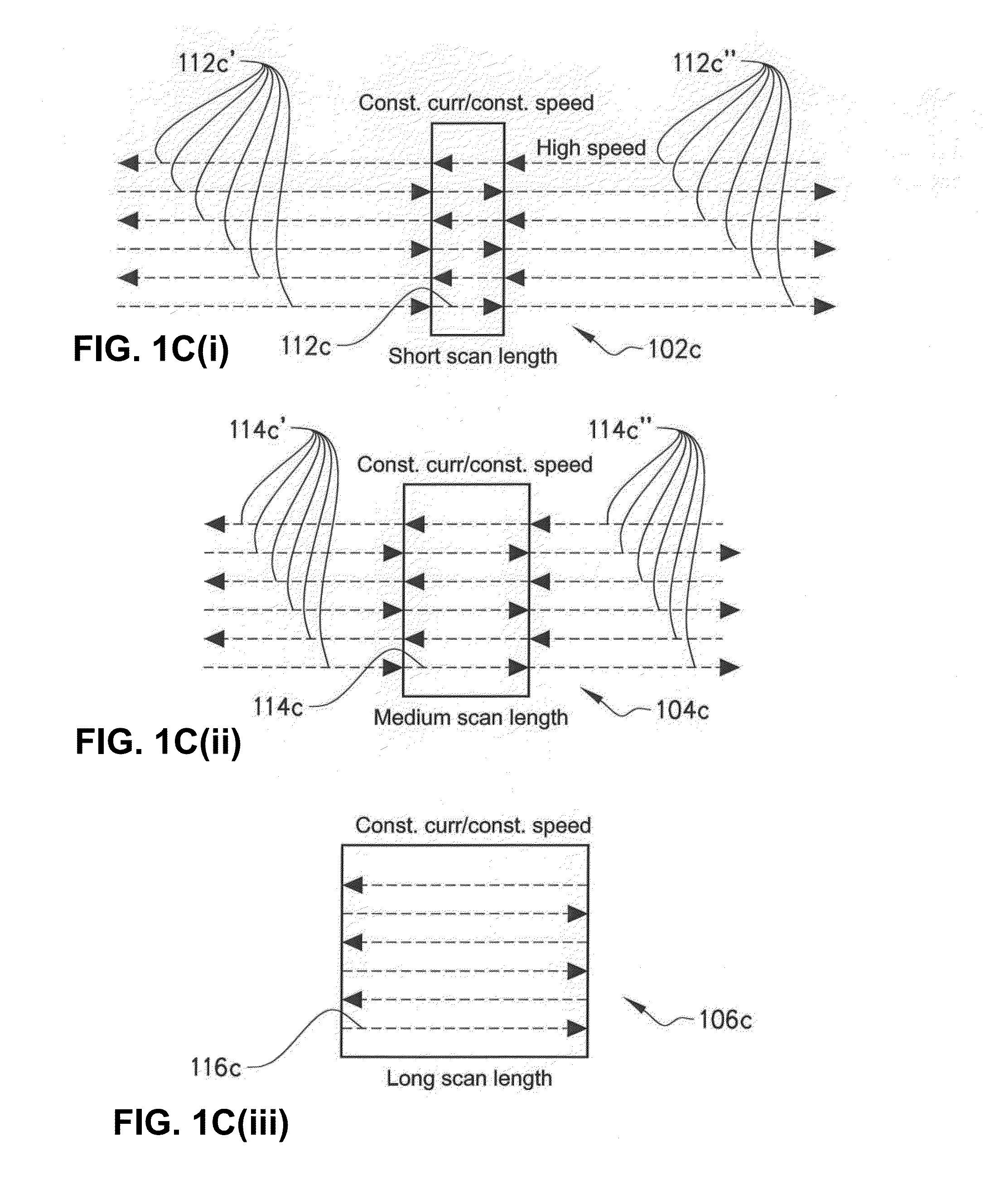
[0051]FIGS. 1C(i)-1C(iii) depict an inventive hatch algorithm according to the present invention for three different layers 102c, 104c and 106c of a three-dimensional article. The topmost layer is narrower than the middle layer, which in turn is narrower than the lowermost layer in the scanning direction. In the exemplified embodiment in FIGS. 1C(i)-1C(iii) the energy from the energy beam is constant and the same for all three layers. The energy beam may be an electron beam or a laser beam. In case of an electron beam the electron beam current is fixed for all three layers and in the case of a laser beam the laser beam power is fixed for all three layers. In the exemplified embodiment in FIGS. 1C(i)-1C(iii) the scanning speed is also constant and the same for all three layers. In another embodiment the scanning speed may alter during the scanning length for at least some of the scanning lines.

[0052]The first layer 102c is exemplified by having 6 scanning lines 112c. Every second sca...


PUM

PropertyMeasurementUnit
Timeaaaaaaaaaa
Poweraaaaaaaaaa
Speedaaaaaaaaaa

Abstract

The invention relates to a method for forming a three-dimensional article through successive fusion of locations of a powder bed. The method comprising: providing a model of said three-dimensional article; applying a powder layer on a work table; determining a maximum scan length of an energy beam; directing said energy beam from a first energy beam source over said work table with constant energy causing said first powder layer to fuse in first selected locations according to said model to form a first cross section of said three-dimensional article, wherein locations with a shorter scan length than said maximum scan length is provided with a time sink before and/or after said scan line so that the time period between each two adjacent scan lines is constant throughout the manufacture of said three-dimensional article.

Description

CROSS-REFERENCE TO RELATED APPLICATIONS[0001]This application claims priority to and the benefit of U.S. Provisional Patent Application Ser. No. 61 / 919,090, filed Dec. 20, 2013, the contents of which as are hereby incorporated by reference in their entirety.BACKGROUND[0002]1. Related Field[0003]The present invention relates to a method for additive manufacturing of three-dimensional articles.[0004]2. Description of Related Art[0005]Freeform fabrication or additive manufacturing is a method for forming three-dimensional articles through successive fusion of chosen parts of powder layers applied to a worktable. A method and apparatus according to this technique is disclosed in US 2009 / 0152771.[0006]Such an apparatus may comprise a work table on which the three-dimensional article is to be formed, a powder dispenser, arranged to lay down a thin layer of powder on the work table for the formation of a powder bed, a ray gun for delivering energy to the powder whereby fusion of the powder...

Claims


Application Information

Patent Timeline
IPC IPC(8): B23K15/00B23K26/08B23K26/34B23K15/02B23K15/10
CPCB23K15/0086B23K15/02B23K26/08B23K26/345B23K15/10B29C64/153B29C64/393B29C64/182Y02P10/25B22F10/28B22F12/44B22F12/52B22F12/30B22F12/84B22F12/90
Inventor ELFSTROEM, ISAKHELLESTAM, CALLEFAGER, MATTIAS
Owner ARCAM AB
Why Eureka
Try Eureka