Method and device for reinforcing and/or lining material

a technology of reinforcing material and reinforcing elements, applied in the field of mechanical engineering, material science and construction, can solve the problems of insufficient material stability or insufficient stability of the anchoring in the porous material, adverse effects on the load bearing capacity of the joining element-material connection, and the long-term stability of the anchoring, so as to reduce energy loss, improve the efficiency of the process, and facilitate the design and handling of the tool

Active Publication Date: 2015-06-25
WOODWELDING
View PDF6 Cites 13 Cited by
  • Summary
  • Abstract
  • Description
  • Claims
  • Application Information

AI Technical Summary

Benefits of technology

[0080]In embodiments of all aspects, the surface of the tool (for example sonotrode if the energy impinges through mechanical vibration) that is in contact with the reinforcement and/or lining element and through which the mechanical energy is coupled into the reinforcement and/or lining element may be generally flat (radial, i.e. perpendicular to the proximodistal axis) or may be tapered or have any other shape. A particularly advantageous combination is the combination of a reinforcement and/or lining element fulfilling condition B. with a flat tool contact face. One reason for this is that the design and handling of the tool is easier when the surface is flat, while the advantages of non-flat contact faces (namely, direct, targeted onset of liquefaction, displacement of the liquefied material into the porous material) can be achieved also if condition B. is fulfilled.
[0081]In condition C, in the telescoping region (where the tool and the auxiliary element are in sliding contact), the tool may include inward projections, such as (axial and/or circumferential) ridges, spheres, etc. In addition or as an alternative, the auxiliary element

Problems solved by technology

If screws or other joining elements are anchored in material, especially porous material, for example, wood, composite (such as chipboard, particle board, oriented strand board etc.), cardboard, concrete, brick, plaster, stone (such as sandstone), sandwich structures comprising hard cover layers and a comparably softer filling between the cover layers, or industrial foam, often the problem of insufficient material stability or insufficient stability of the anchoring in the porous material arises.
Especially,

Method used


Image

  • Method and device for reinforcing and/or lining material
  • Method and device for reinforcing and/or lining material
  • Method and device for reinforcing and/or lining material

Examples


Embodiment Construction

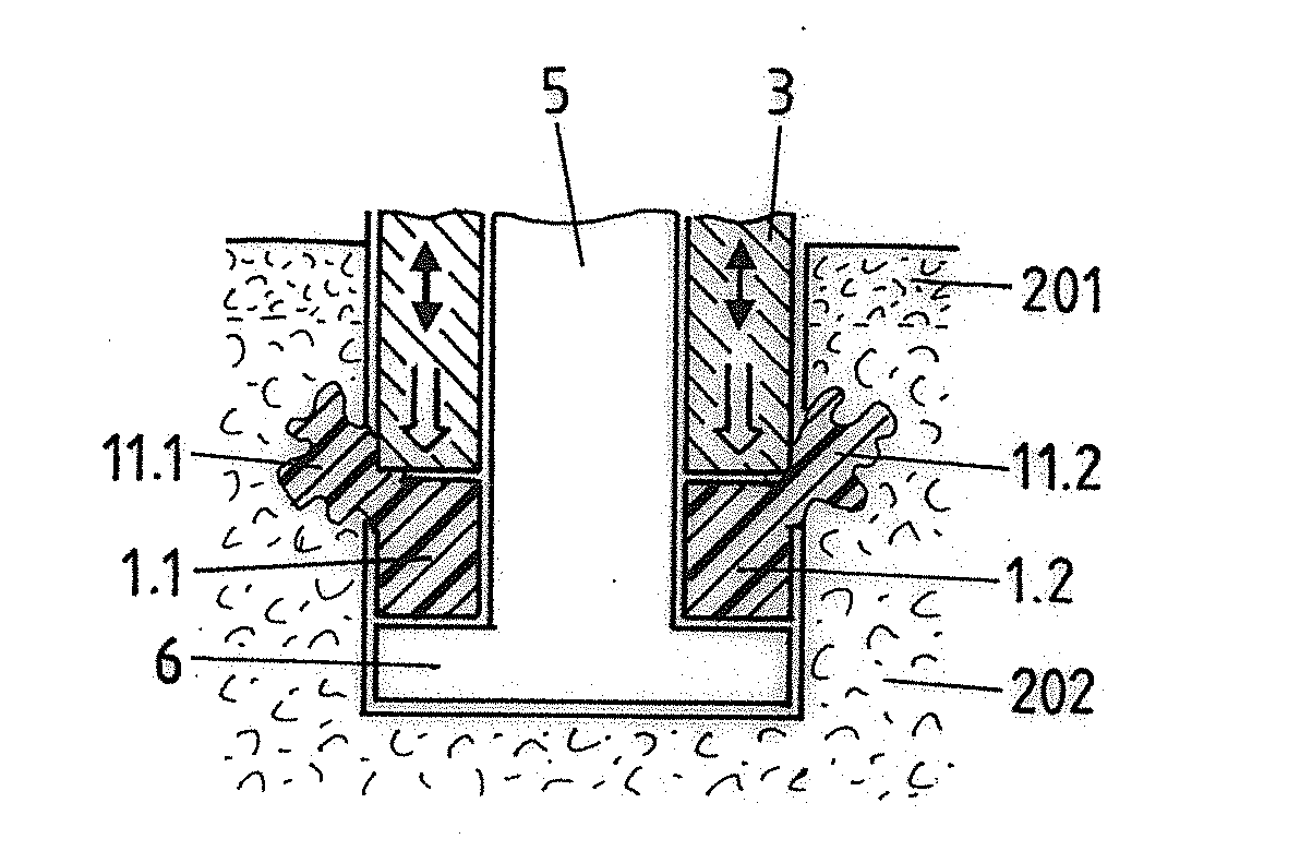
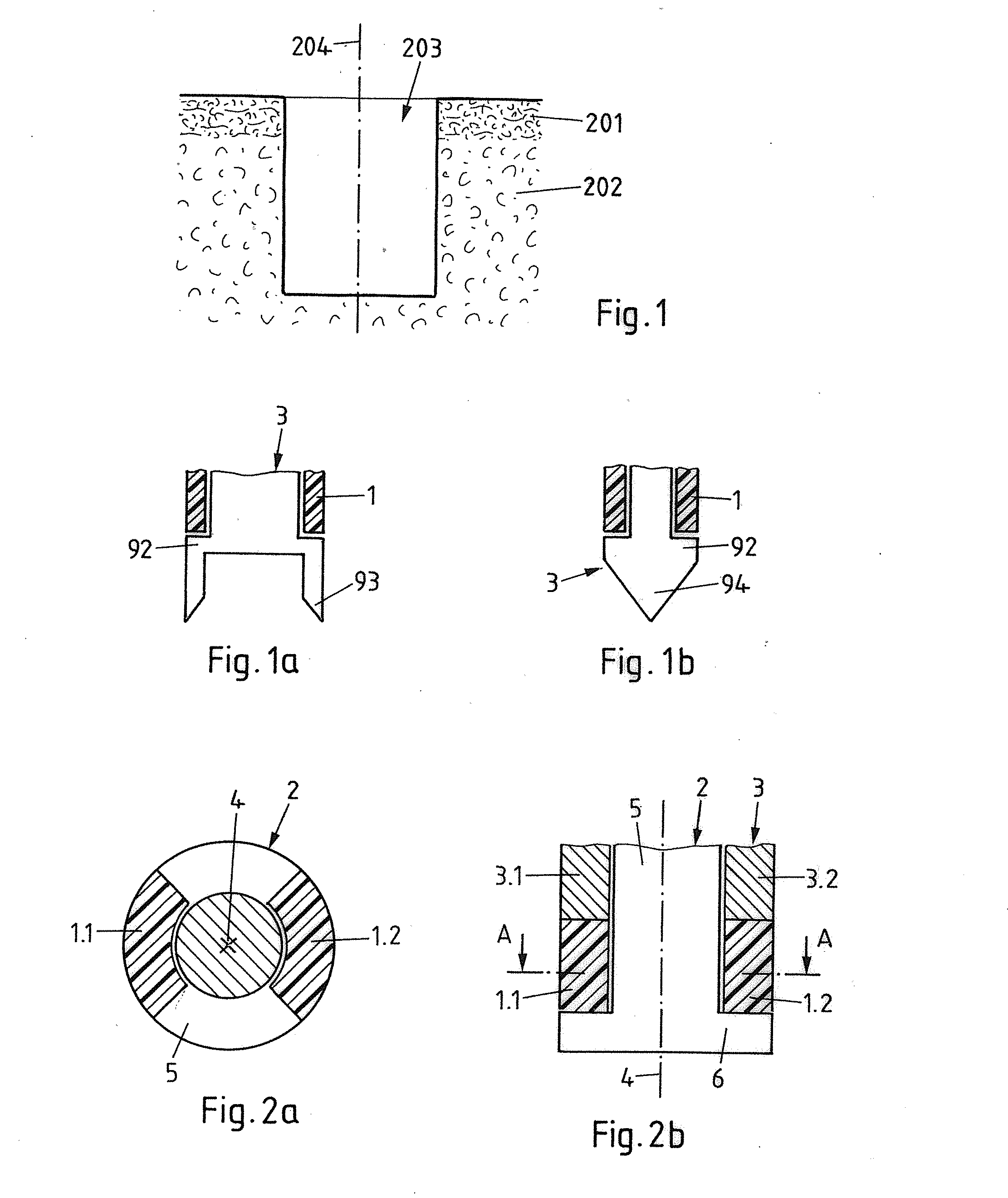
[0191]FIG. 1 shows a portion of porous material, for example of a board of a composite or sandwich material. The depicted porous material includes a top layer of comparably dense and hard covering material 201, for example, laminated onto less dense composite porous material 202. An initial opening 203, in which a joining element—such as, for example, a screw or a pin—is to be anchored, has, for example, been made by drilling. Alternatively, the initial opening 203 may have been pre-processed during the building object manufacturing process. An opening axis 204 is shown. In case the opening is made by drilling, the opening may have rotational symmetry with respect to the axis 204. Because of the relatively low mechanical load resistance of the brittle composite porous material, it is desirable to improve the mechanical stability of the porous material prior to the anchoring of the joining element.

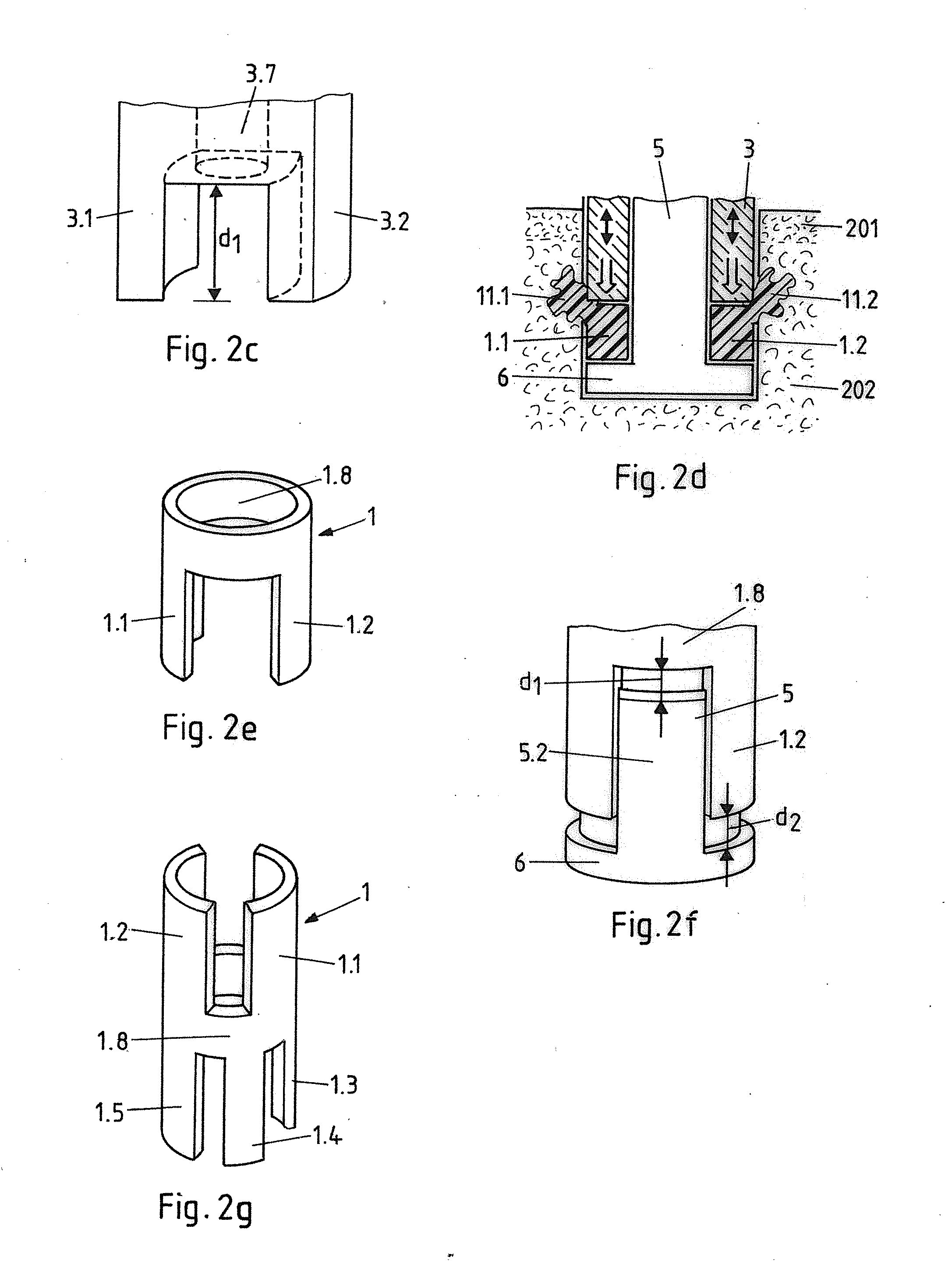
[0192]In accordance with the fifth aspect of the invention, an initial opening 203 is m...


PUM

PropertyMeasurementUnit
Fractionaaaaaaaaaa
Widthaaaaaaaaaa
Forceaaaaaaaaaa

Abstract

A reinforcement and/or lining method is provided, wherein a thermoplastic reinforcement and/or lining element is subject to mechanical energy impact and mechanical pressure by a tool so that reinforcement and/or lining material of the reinforcement and/or lining element is liquefied and pressed into porous material to reinforce the porous material. In at least one axial depth, the reinforcement and/or lining element is segmented as a function of the circumferential angle so that at this axial depth the circumferential wall of the initial opening in first regions is in contact with the reinforcement and/or lining element and in second regions is not in contact with the reinforcement and/or lining element.

Description

BACKGROUND OF THE INVENTION[0001]1. Field of the Invention[0002]The invention is in the fields of mechanical engineering, material science and construction, especially material engineering, building industry, timber construction, furniture industry and mechanical construction. In particular, it relates to methods and apparatuses for lining and / or reinforcing material.[0003]2. Description of Related Art[0004]If screws or other joining elements are anchored in material, especially porous material, for example, wood, composite (such as chipboard, particle board, oriented strand board etc.), cardboard, concrete, brick, plaster, stone (such as sandstone), sandwich structures comprising hard cover layers and a comparably softer filling between the cover layers, or industrial foam, often the problem of insufficient material stability or insufficient stability of the anchoring in the porous material arises. Especially, in composite materials, any load acting on the joining element is passed...

Claims


Application Information

Patent Timeline
IPC IPC(8): B29C65/08E04B1/92
CPCB29C65/08B29K2101/12E04B1/92B29L2031/7278B29C65/0681B29C65/081B29C65/1674B29C65/18B29C65/7437B29C65/7443B29C66/02242B29C66/032B29C66/1122B29C66/3022B29C66/30326B29C66/304B29C66/348B29C66/474B29C66/727B29C66/7392B29C66/7461B29C66/7487B29C66/8322B29C65/06B29C66/9512B29C66/9516B29C66/9513B29C66/9517B29C66/7212B29C66/72143B29C66/72141B29C65/1412B29C65/1487B29C65/1609B29C65/1612B29C65/1687B29C65/1409B29C66/71B29C66/73161B29C66/21B29C66/723B29C66/7463B29C66/7486B29C66/746B29C65/02B29L2007/002B29C63/0069B29C63/341B29K2307/04B29K2309/08B29K2277/10B29K2023/12B29K2025/06B29K2025/08B29K2027/06B29K2033/12B29K2055/02B29K2059/00B29K2067/00B29K2069/00B29K2071/00B29K2077/00B29K2079/085B29C65/3412B29C65/3476B29C65/3404F16B5/01B29C66/721B29C65/34
Inventor MAYER, JORGAESCHLIMANN, MARCEL
Owner WOODWELDING
Why Eureka
Try Eureka