
Method for Producing at least One Component and Open-Loop and/or Closed-Loop Control Device

a control device and component technology, applied in the direction of liquid surface applicators, solid-state diffusion coatings, coatings, etc., can solve the problems of difficult diffusion of donor gases within the charge and/or within the interior geometries, such as blind hole bores, and the inability to ensure a continuous uptake of carbon and nitrogen

Inactive Publication Date: 2015-06-25
ROBERT BOSCH GMBH
View PDF6 Cites 0 Cited by
  • Summary
  • Abstract
  • Description
  • Claims
  • Application Information

AI Technical Summary

Benefits of technology

The invention provides a process and control device for producing components by simultaneously introducing a carbon-emitting gas and a nitrogen-emitting gas into a treatment chamber, allowing for continuous carbon and nitrogen uptake. This reduces process times and allows for homogeneous carburizing and nitrogenizing even in complex component geometries. The control device allows for a specified ratio between the carbon and nitrogen concentrations to be set, influencing the properties of the material and component.

Problems solved by technology

Due to the alternating carbon and nitrogen offering phases, caused as a result of the process, it is not possible to ensure a continuous uptake of carbon and nitrogen.
In the case of this carbonitriding process, the high treatment temperatures of 1100 to 1200° C. and the atmospheric pressure are problematic.
In addition, the process gas pressure of 1 bar makes the diffusion of the donor gases within the charge and / or within interior geometries, such as for example blind-hole bores, considerably more difficult.
Furthermore, at these temperatures, low-cost metallic materials have a tendency to form coarse grains, which can have adverse effects on the durability of the component, as a result of which more expensive materials have to be used and / or an additional heat treatment step has to be carried out to make the grains fine.

Method used


Image

  • Method for Producing at least One Component and Open-Loop and/or Closed-Loop Control Device
  • Method for Producing at least One Component and Open-Loop and/or Closed-Loop Control Device
  • Method for Producing at least One Component and Open-Loop and/or Closed-Loop Control Device

Examples


Embodiment Construction

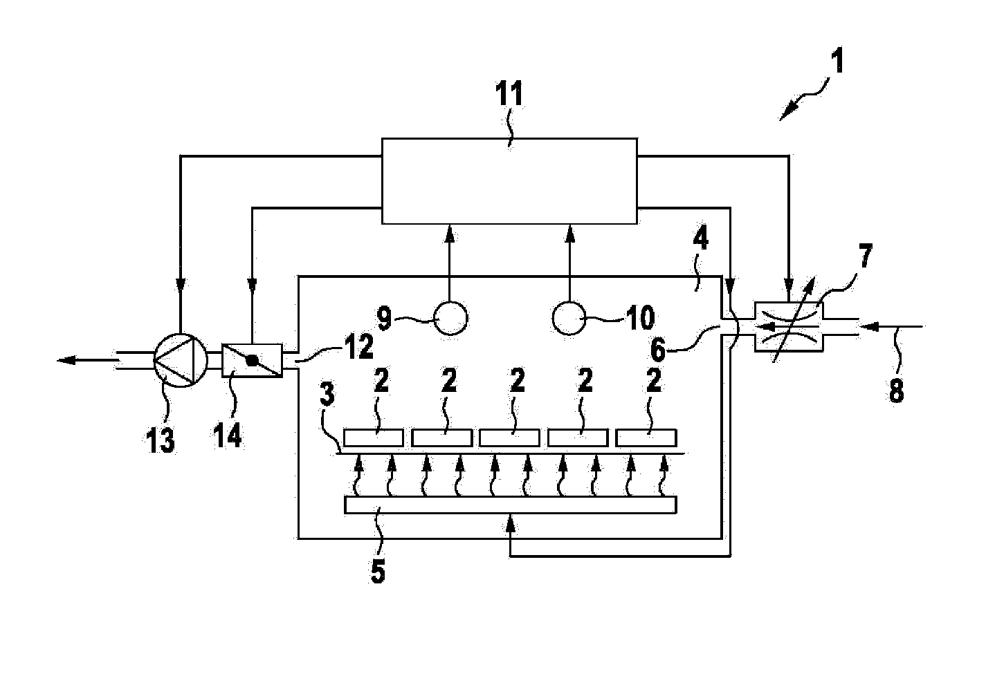
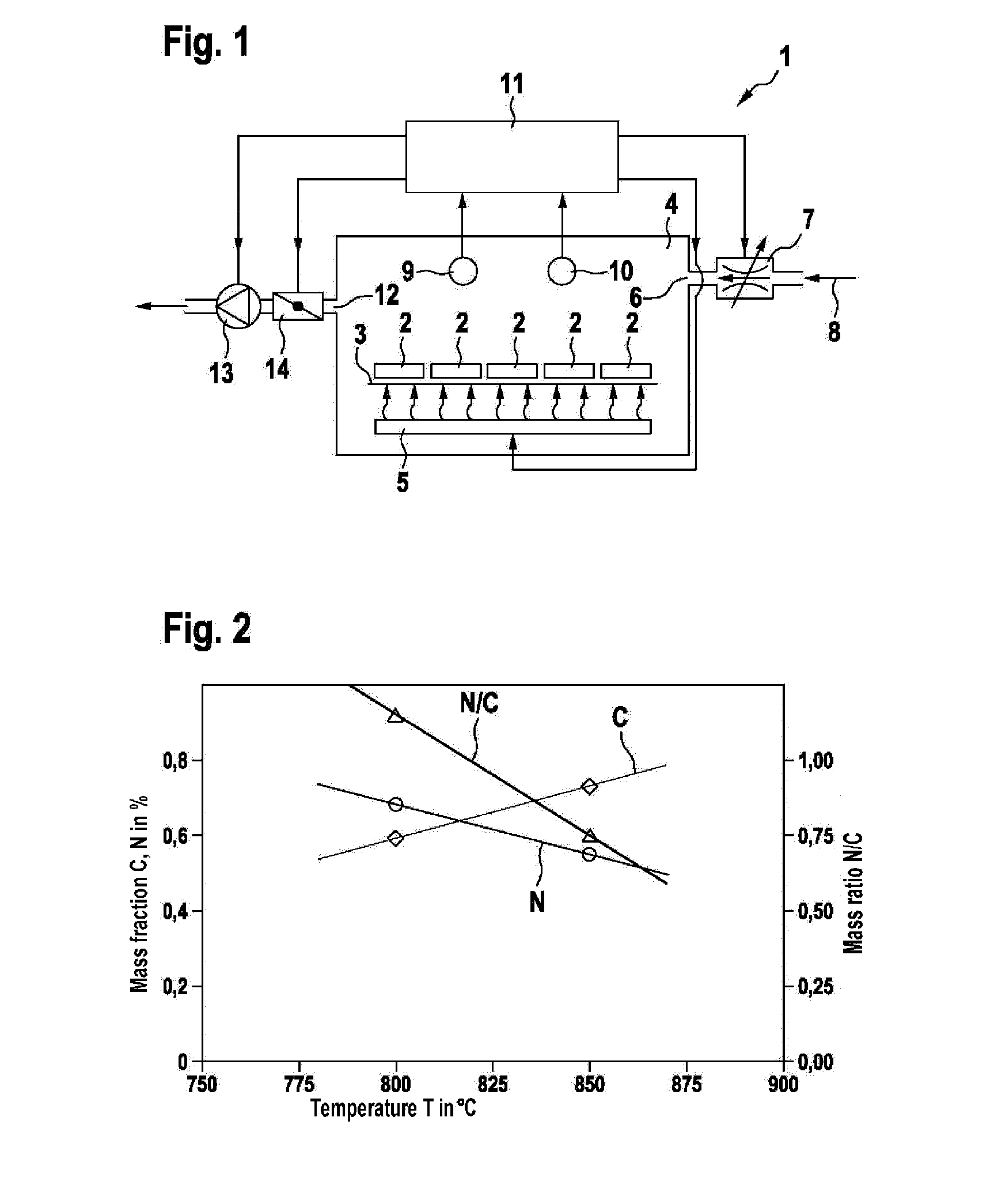
[0033]FIG. 1 shows a schematic representation of a plant 1 for the low-pressure carbonitriding of one or more components 2. In FIG. 1, five components 2 are represented by way of example. The components 2 are arranged on a support 3 in a treatment chamber 4. The components 2 can be heated by means of a heating device 5 represented in the lower region of the drawing. An inlet 6 with an associated flow control valve 7 allows the introduction of a carbon- and nitrogen-donor gas 8. A temperature sensor 9 and a pressure sensor 10 are arranged in the upper region of the drawing of the treatment chamber 4. An open-loop and / or closed-loop control device 11 shown above them receives the signals coming from the temperature sensor 9 and the pressure sensor 10. An outlet 12 of the treatment chamber 4 leads to the input of a pump 13, which may be formed for example as a vacuum pump. Arranged upstream of the pump 13 is a throttle 14, in particular for controlling the pressure.

[0034]During the ope...


PUM

PropertyMeasurementUnit
pressureaaaaaaaaaa
temperatureaaaaaaaaaa

Abstract

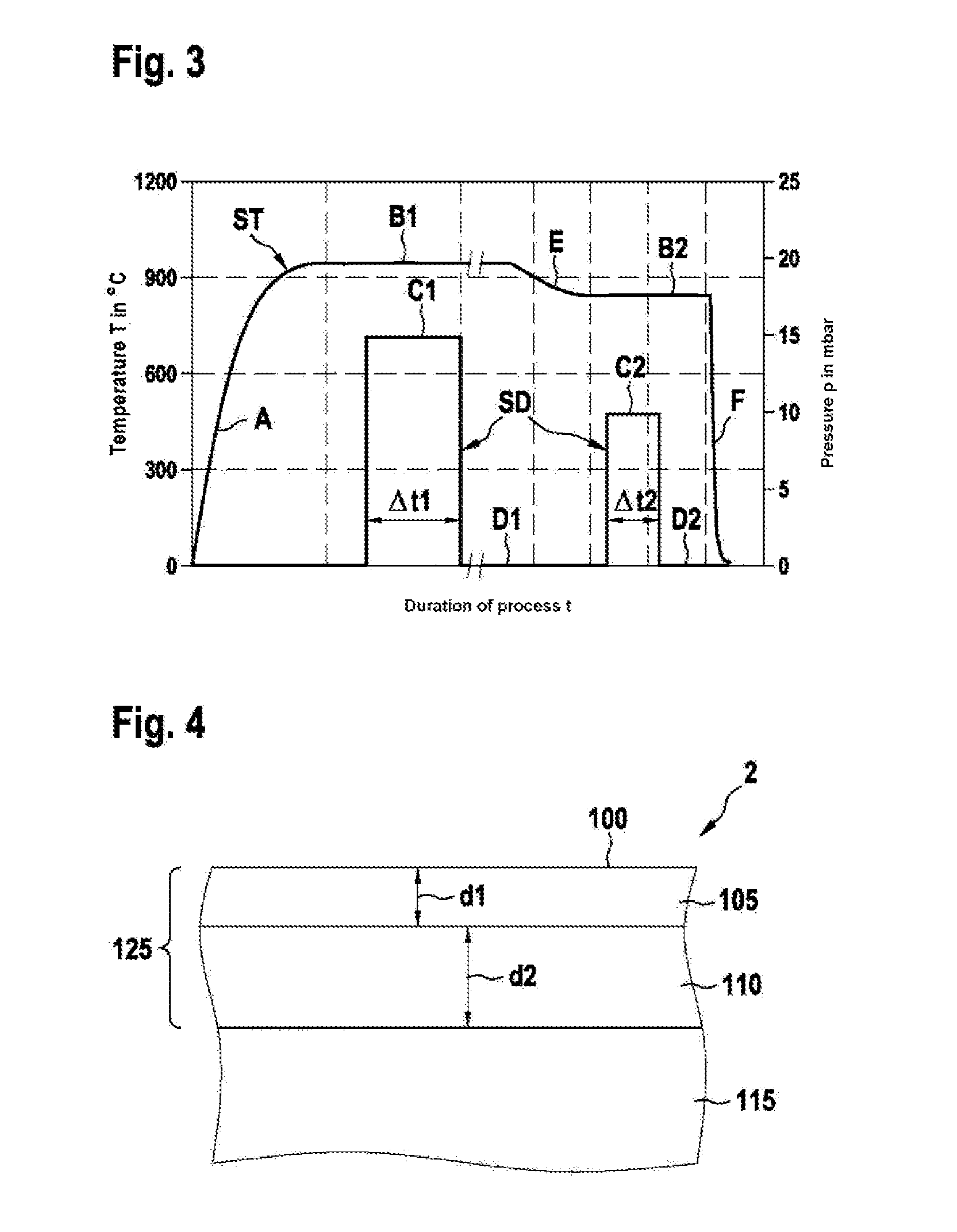
The disclosure relates to a method for producing at least one, in particular metal, component, preferably a cylinder head, a nozzle body for a high-pressure injection pump, a component of a diesel injection engine, or a throttle disk, by means of low-pressure carbonitriding in at least one treatment chamber, which preferably can be evacuated, and an open-loop and / or closed-loop control device, which enables the setting of a specified ratio between a carbon concentration and a nitrogen concentration in a surface layer of the at least one component. In at least one treatment phase, a carbon-providing gas and a nitrogen-providing gas are simultaneously introduced into the treatment chamber. Based on a specified ratio between a carbon concentration and a nitrogen concentration to be absorbed by the at least one component in a surface layer of the component, a target value for the temperature and / or the pressure to be set in the treatment chamber is determined and is set in the treatment chamber for a specified time.

Description

[0001]The present invention relates to a method for producing at least one component and to an open-loop and / or closed-loop control device of the generic type of the independent claims.PRIOR ART[0002]The document DE 199 09 694 A1 describes a carbonitriding process in which the inward diffusion of the nitrogen takes place during the entire process or, if elemental nitrogen is used as the donor gas, preferably only in the last process phase. Molecular nitrogen, ammonia and other nitrogen-containing compounds are mentioned in particular as nitrogen donors. Carbon donors are not specified.[0003]The document DE 101 18 494 C2 describes a low-pressure carbonitriding process in which steel parts are first carburized and subsequently nitrogenized with a nitrogen-donor gas. Acetylene, propane and ethylene are specified as carbon donors. A donor gas that contains ammonia is mentioned as the nitrogen donor. Nothing further is specified about the nitrogen donor.[0004]The document DE 103 22 255 A...

Claims


Application Information

Patent Timeline
Patent Type & Authority Applications(United States)
IPC IPC(8): C23C8/30
CPCC23C8/30C23C8/00C23C8/02C23C8/32C23C8/34C23C8/80
Inventor KOCH, DAVIDBAJOHR, SIEGFRIEDHAGYMASI, LASZLOBUCHHOLZ, DOMINICREIMERT, RAINERWALDENMAIER, THOMAS
Owner ROBERT BOSCH GMBH
Learn More