Underwater vehicle and sensor

a sensor and underwater technology, applied in underwater equipment, special-purpose vessels, instruments, etc., can solve the problems of limited data collection, high cost of vehicles, and large sensors, and achieve the effect of increasing the number of sensors

a sensor and underwater technology, applied in underwater equipment, special-purpose vessels, instruments, etc., can solve the problems of limited data collection, high cost of vehicles, and large sensors, and achieve the effect of increasing the number of sensors

US20150177212A1Active Publication Date: 2015-06-25CHEVROU USA INC

Image

  • Underwater vehicle and sensor
  • Underwater vehicle and sensor
  • Underwater vehicle and sensor

Examples


Embodiment Construction

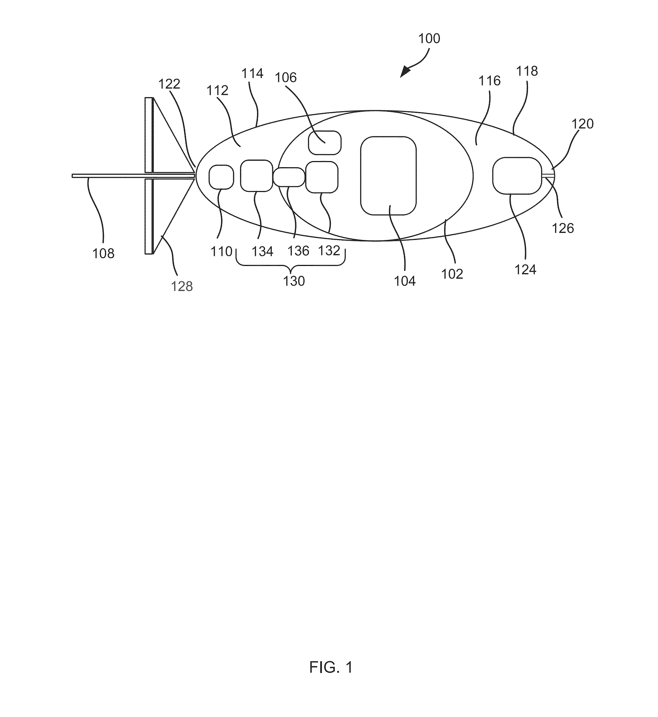
[0050]An underwater vehicle used in accordance with an embodiment of the present invention can be any suitable vehicle adapted to travel at an appropriate depth (e.g., 1,000-6,000 m) and adapted to carry a water sampling and sensor arrangement as described below.

[0051]1. Autonomous Underwater Vehicle

[0052]In accordance with the embodiment shown in FIG. 1, the underwater vehicle is an autonomous underwater vehicle (AUV) 100, for example of the type described in U.S. Pat. No. 8,381,672 entitled “Systems and methods for compensating for compressibility and thermal expansion coefficient mismatch in buoyancy controlled underwater vehicles” which is hereby incorporated by reference.

[0053]The AUV 100 includes a pressure hull 102 that provides a sealed compartment, an aft cavity 112 formed by the aft fairing 114, and a forward cavity 116 formed by the forward fairing 118. Both the aft and forward cavities 112, 116 have a generally elliptical ogive shape or another suitable hydrodynamic shap...


PUM

PropertyMeasurementUnit
depthsaaaaaaaaaa
depthaaaaaaaaaa
speedaaaaaaaaaa

Abstract

Described herein is an underwater vehicle having a vehicle body with a buoyancy controller adapted to vary the buoyancy of the vehicle in order to control motion of the vehicle through an underwater environment. The vehicle further includes a sampling system and a sensor arrangement. The sampling system is adapted to sequentially sample fluid from the underwater environment at specified sampling times resulting in a sample sequence, each sample associated with a sample time and a fluid flow rate. The sensor arrangement includes a plurality of molecule sensors adapted to sense organic molecules in each respective sample of the sample sequence.

Description

FIELD OF THE INVENTION[0001]The invention relates to the field of hydrocarbon detection, and particularly to a sampling system and sensor for detecting organic molecules such as hydrocarbons, which may be used with an underwater vehicle. This application claims priority to U.S. Provisional Patent Application No. 61 / 918,410 filed Dec. 19, 2013, which is fully incorporated herein by reference.BACKGROUND OF THE INVENTION[0002]Various techniques can be used to collect data relating to underwater hydrocarbon reserves (e.g., to detect the presence of naturally occurring seafloor seepage) or relating to underwater infrastructure transporting fluid that contains hydrocarbons (e.g., to assess pipeline integrity). Reflection seismology or non-seismic detection technologies such as magnetometers are typically used. More specifically for a marine environment, satellite and airborne imaging, or shipborne multibeam imaging together with drop core sampling are often used.[0003]To gather data close...

Claims


Application Information

Patent Timeline
25 Jun 2015
Publication
US20150177212A1
IPC
G01N33/18; B63G8/00; B63G8/08; B63G8/14
CPC
G01N33/1826; B63G8/14; B63G2008/005; B63G8/08; B63G8/001; B63G2008/004; E02D1/00; G01N1/12
Inventors
THOMAS, DAVID GLYNN; KALLI, CHRISTOPHER JOHN