Adapter for replaceable lamp

a technology for adapters and lamps, applied in the direction of lighting and heating apparatus, coupling device connections, furnaces, etc., can solve the problems of waste and expense, and achieve the effect of rapid thermal processing

Inactive Publication Date: 2015-06-25
APPLIED MATERIALS INC
View PDF9 Cites 6 Cited by
  • Summary
  • Abstract
  • Description
  • Claims
  • Application Information

AI Technical Summary

Benefits of technology

[0008]Embodiments of the disclosure generally relate to an improved adapter for lamps used as a source of heat radiation in a rapid thermal processing (RTP) chamber. In one embodiment of the present disclosure, a lamp assembly is provided. The lamp asse

Problems solved by technology

Replacement of a functional base due to a fau

Method used


Image

  • Adapter for replaceable lamp
  • Adapter for replaceable lamp
  • Adapter for replaceable lamp

Examples


Embodiment Construction

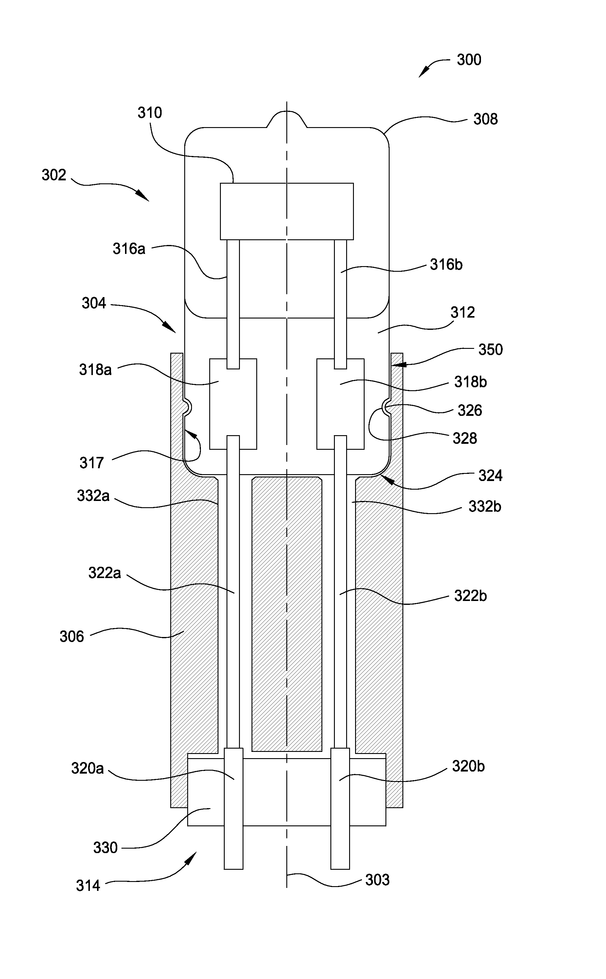
[0019]Embodiments of the disclosure generally relate to an improved adapter for lamps used as a source of heat radiation in a rapid thermal processing (RTP) chamber. The improved adapter allows an easy, fast replacement of a lamp element by making the lamp element removably engaged with the adapter so that the lamp element and / or the adapter can be individually replaced. In some aspects of various embodiments of this disclosure, the adapter may be permanently affixed (brazed, welded, interference fit, or glued etc.) in the lamphead assembly. The lamp element is configured to provide sufficient rigidity to handle compressive forces of inserting the lamp assembly into a PCB structure. The adapter may optionally provide a fuse (and / or electrical receptacles for the lamp element) which can be replaced from the side, top, or bottom of the adapter. The adapter provides a receptacle for receiving a portion of the lamp element. The receptacle is contoured and may be coated to aid in directi...


PUM


Abstract

Embodiments of the present disclosure generally relate to an improved adapter for simplified lamps for use as a source of heat radiation in a rapid thermal processing (RTP) chamber. In one embodiment, a lamp assembly is provided. The lamp element includes a capsule having a filament disposed therein, a press seal extending from the capsule, and an adapter having a receptacle contoured to receive at least a portion of the press seal, wherein the press seal is removably engaged with the adapter.

Description

CROSS-REFERENCE TO RELATED APPLICATIONS[0001]This application claims priority to U.S. Provisional Patent Application Ser. No. 61 / 918,451, filed on Dec. 19, 2013, which herein is incorporated by reference.BACKGROUND[0002]1. Field[0003]Embodiments of the present disclosure generally relate to an apparatus for thermally processing a substrate. In particular, embodiments of the present disclosure relate to an adapter for lamps used as a source of heat radiation in a rapid thermal processing (RTP) chamber.[0004]2. Description of the Related Art[0005]During RTP of substrates, thermal radiation is generally used to rapidly heat a substrate in a controlled environment to a maximum temperature of up to about 1350° C. This maximum temperature is maintained for a specific amount of time ranging from less than one second to several minutes depending on the particular process. The substrate is then cooled to room temperature for further processing.[0006]High voltage, e.g., about 40 volts to abou...

Claims


Application Information

Patent Timeline
IPC IPC(8): H01K1/46H01K1/66H05B3/00H01K1/36
CPCH01K1/46H05B3/0038H01K1/66H01K1/36H01K1/44
Inventor RANISH, JOSEPH M.SEREBRYANOV, OLEG V.
Owner APPLIED MATERIALS INC
Why Eureka
Try Eureka