Pulse Forming Network And Pulse Generator

a pulse generator and pulse forming network technology, applied in the field of pulse generators, can solve the problems of undesirable effects, high temperature required to anneal the device side, and low energy output of the pulse generator, and achieve the effect of greatly attenuating the energy of the pulse discharged

Inactive Publication Date: 2007-08-30
T SQUARED THERMAL TECH
View PDF4 Cites 10 Cited by
  • Summary
  • Abstract
  • Description
  • Claims
  • Application Information

AI Technical Summary

Benefits of technology

[0034] Furthermore, in accordance with some preferred embodiments of the present invention, the device is incorporated in a system for rapid thermal processing.
[0048] thereby causing the energy of the pulse to discharge also through the first resistor, thus extinguishing or greatly attenuating the energy of the pulse discharged through the load.

Problems solved by technology

The ion implantation process damages the crystal lattice structure of the surface region of the wafer, and leaves the implanted dopant atoms in interstitial sites where they are electrically inactive.
However, the high temperatures required to anneal the device side also tend to produce undesirable effects using existing technologies.
As performance demands of semiconductor wafers increase and device sizes decrease, it is necessary to produce increasingly shallow and abruptly defined junctions, and therefore, diffusion depths that would have been considered negligible in the past or that are tolerable today will be unacceptable in the next few years and thereafter.
Flashlamp and laser thermal pulse generators, as ultra-fast annealing tools for semiconductor wafers, were discovered, invented, and researched in the mid and late seventies, but were abandoned by tool makers in the mid eighties because the technological demands did not justify their development.
There is a considerable overshoot of the electrical pulse and thermal flash after executing the means proposed in ‘447’, due to a large amount of residual energy still flowing through the load.
Thus, a more optimal flash is produced, but even the partial control of the amount of termination of the flash which existed in the “632” publication, is lost.

Method used


Image

  • Pulse Forming Network And Pulse Generator
  • Pulse Forming Network And Pulse Generator
  • Pulse Forming Network And Pulse Generator

Examples


Embodiment Construction

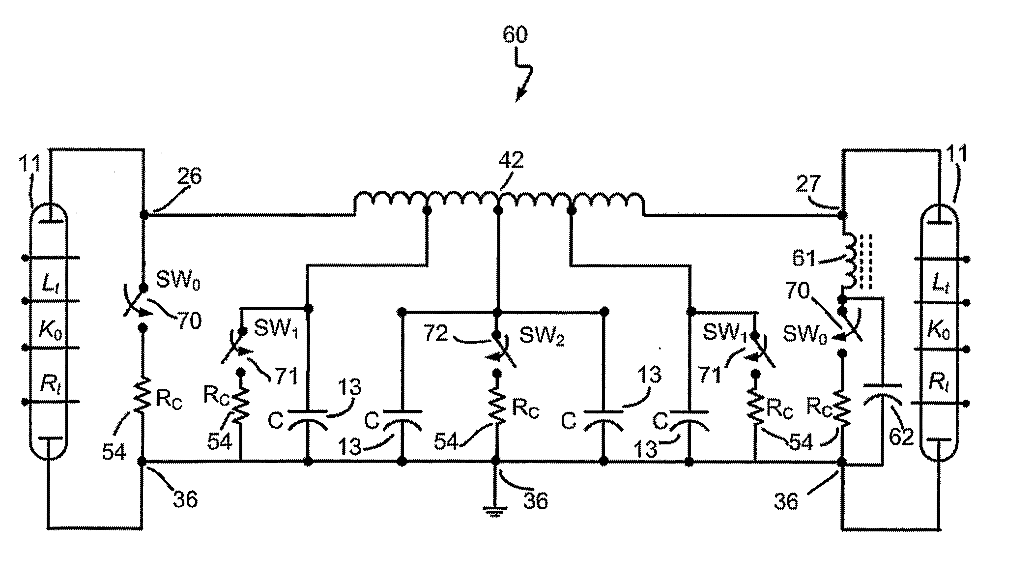
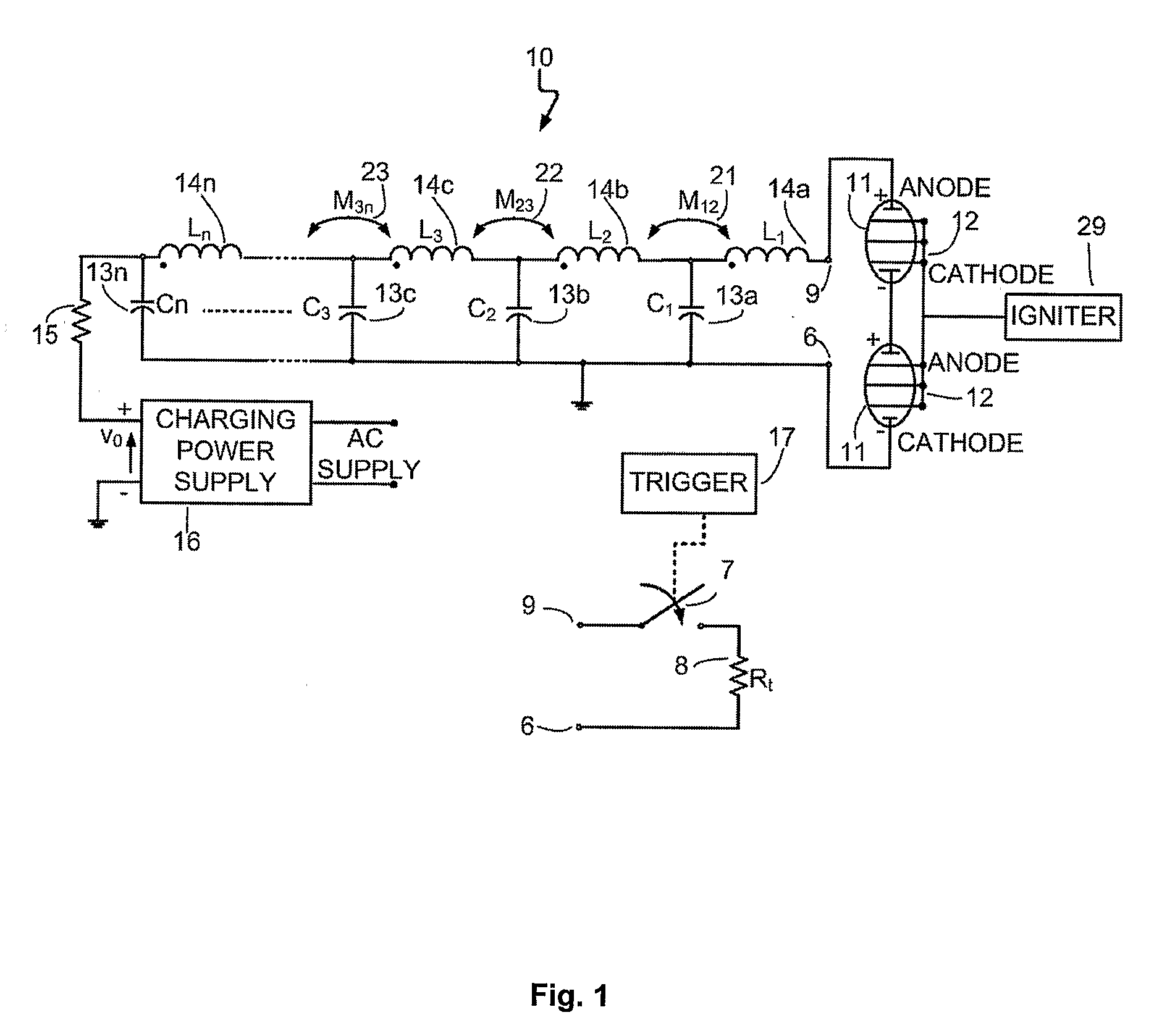
[0092] The present invention aims at providing a high power apparatus or pulse generator, and a method for generating a pulse of high energy and controlled duration (width) into a resistive load such as a flashlamp. The resulting pulse contains two distinct characteristics. The first characteristic is a unique temporal shape of the pulse, which results in an increase in the electrical power delivered to the load towards the end of the pulse just before fall time commences. This pulse shaping is advantageous for applications such as flashlamp annealing (FLA) of the front (active) side of a silicon wafer. The amount of shaping or increase in the electrical pulse power at the late part of the pulse is controlled beforehand by the operator, and is achieved with no alteration of the characteristic output impedance of the generator, which should be matched to that of the load such as a bank of flashlamps.

[0093] With regard to the second characteristic of the resulting pulse, the present ...


PUM


Abstract

A pulse forming network is disclosed. The device comprising two pulse forming networks (40), a first pulse forming network comprising n sections, n being an integer, and a second pulse forming network comprising m sections, m being an integer, each of the sections of the first and the second pulse forming networks comprising at least one capacitor and at least one inductor, and each pulse forming network having one output port for connecting a load, the two pulse forming networks electrically connected and magnetically coupled back to back. A method and device for extinguishing an electrical pulse generated by a pulse generator is also disclosed (SWo).

Description

FIELD OF THE INVENTION [0001] This invention relates generally to electrical pulse generation. More particularly the present invention relates to a pulse generator for various high-energy tasks. The pulse generator of the present invention has special appeal in the field of tools and processes that heat a workpiece by directing thermal radiation towards it and optionally spreading that thermal radiation in a uniform manner by some optical means. [0002] In the latter aspect, the present invention relates to a method and apparatus for producing an intense flash of electromagnetic radiation, which typically lasts for about 50 to 5000 microseconds (but not limited to that range). The workpiece in this particular case may be a silicon wafer. A silicon wafer is subjected to many different processes before a complete semiconductor device is realized on the device side of the wafer, which acts as a substrate. One particular family of processes related to this invention is known as Rapid The...

Claims


Application Information

Patent Timeline
Patent Type & Authority Applications(United States)
IPC IPC(8): H03K3/00G01JH03K3/57
CPCH03K3/57H03K3/53
Inventor BARAK, MENASHE
Owner T SQUARED THERMAL TECH
Why Eureka
Try Eureka