

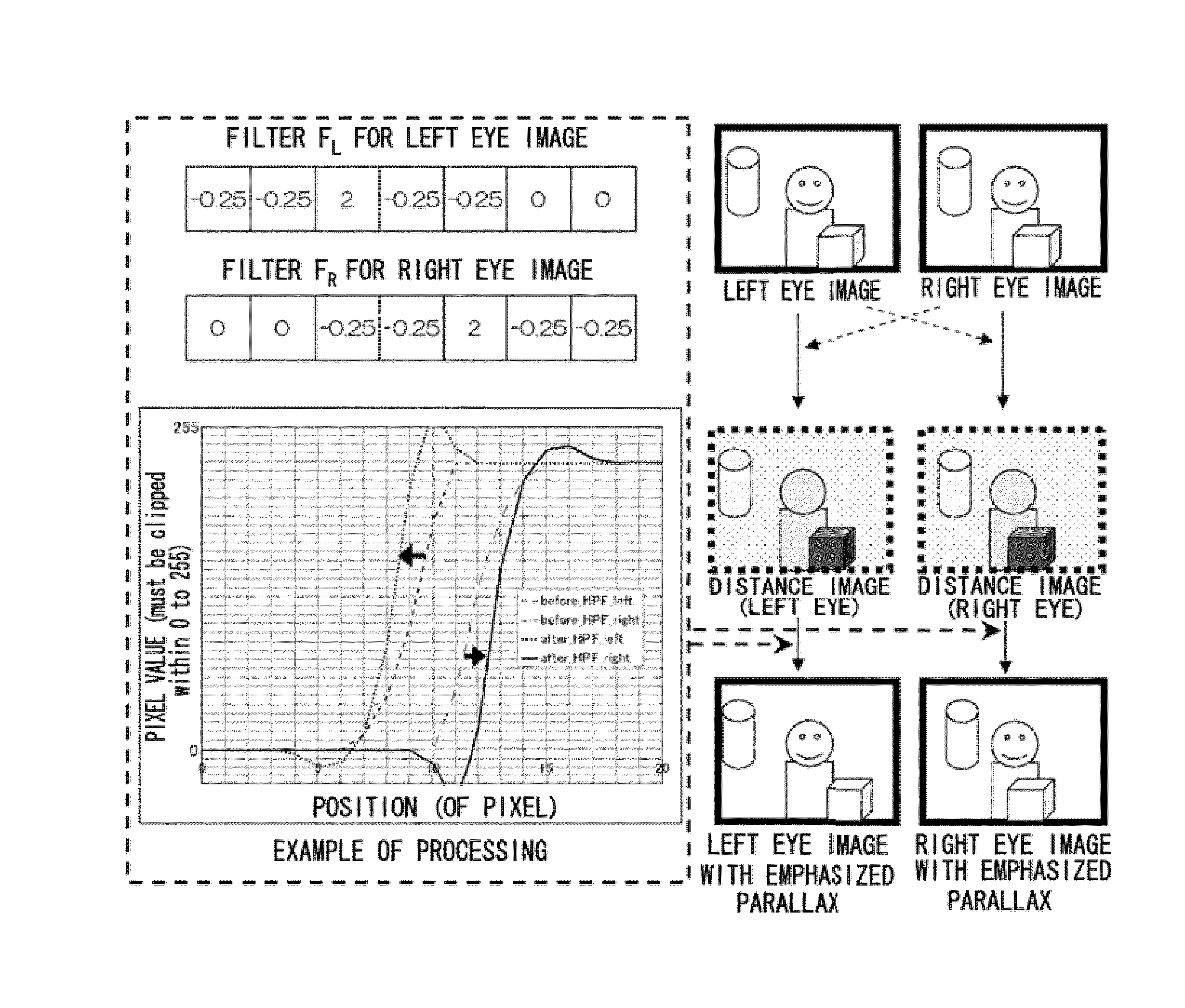
Image processing device, imaging device, image processing method, and computer readable medium
a technology of image processing and imaging device, which is applied in the field of image processing device, imaging device, image processing method, and computer readable medium, can solve the problems of difficult viewing of split images, inability to display contrast at a greater resolution, and inability to accurately focus on the exact focus position (the position of the image) to achieve the effect of suppressing instances of excessive or insufficient parallax emphasis
- Summary
- Abstract
- Description
- Claims
- Application Information
AI Technical Summary
Benefits of technology
Problems solved by technology
Method used
Image

Examples
first exemplary embodiment
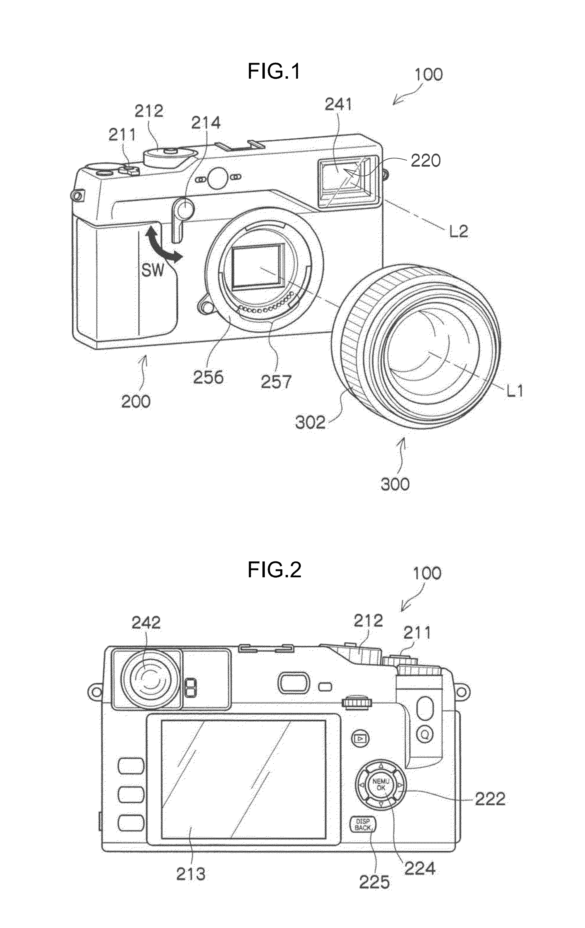
[0069]FIG. 1 is a perspective view illustrating an example of an external appearance of an imaging device 100 according to a first exemplary embodiment. FIG. 2 is a back view of the imaging device 100 illustrated in FIG. 1.
[0070]The imaging device 100 is an interchangeable lens camera, and is a digital camera with a camera body 200 and an interchangeable lens 300 (imaging lens and focusing lens 302 (manual operation section)) that is interchangeably mounted to the camera body 200, and without a reflex mirror. A HYBRID FINDER (registered trademark) 220 is also provided to the camera body 200. HYBRID FINDER 220 indicates, for example, a finder capable of selective operation as an optical viewfinder (referred to as “OVF” below), or as an electronic viewfinder (referred to as “EVF” below).
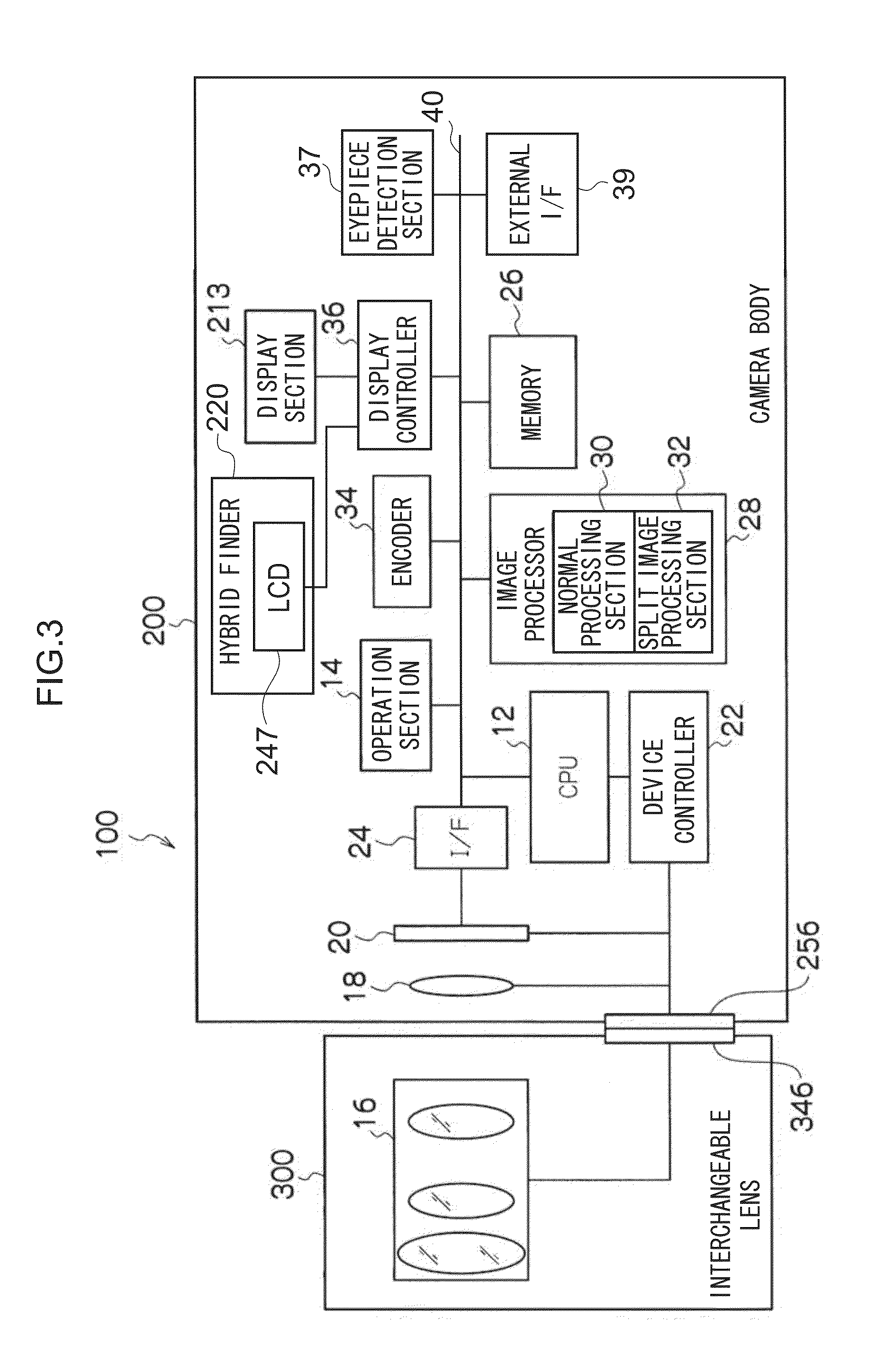
[0071]The camera body 200 and the interchangeable lens 300 are mounted interchangeably by coupling a mount 256 provided to the camera body 200 together with a mount 346 (see FIG. 3) provided on the int...
second exemplary embodiment
[0214]In the first exemplary embodiment, an example is given of the imaging device 100, however modified examples of the imaging device 100 include mobile terminal devices such as, for example, mobile phones and smartphones including a camera function, personal digital assistants (PDAs), mobile gaming devices, or the like. Detailed explanation follows regarding an example of a smartphone, with reference to the drawings.
[0215]FIG. 27 is a perspective view illustrating an example of the external appearance of a smartphone 500. The smartphone 500 illustrated in FIG. 27 includes a flat plate shaped casing 502, and a display and input section 520 provided on one face of the casing 502 and integrating together a display panel 521 serving as a display section and an operating panel 522 serving as an input section. The casing 502 includes a speaker 531, a microphone 532, an operating section 540, and a camera section 541. Note that the configuration of the casing 502 is not limited thereto,...
PUM
 Abstract
Description
Claims
Application Information