Speckle contrast optical tomography

a technology of optical tomography and speckle contrast, which is applied in the field of subsurface tissue blood flow imaging techniques, can solve the problems of many limitations and unsuitability for 3d imaging, and achieve the effects of high speed speckle contrast measurement, low cost and high number

Active Publication Date: 2015-07-02
WASHINGTON UNIV IN SAINT LOUIS +1
View PDF1 Cites 41 Cited by
  • Summary
  • Abstract
  • Description
  • Claims
  • Application Information

AI Technical Summary

Benefits of technology

[0007]The present invention extends high speed speckle contrast measurements to deep tissue, three-dimensional imaging. It addresses the previous weaknesses of optical correlation methods and provides high number of low cost, speckle measurements for three dimensional imaging of blood flow in preclinical and human imaging. The advantages of the invention are the cost effectiveness of speckle detection simplicity and high speed (>100 kHz—per source-detector pair measurement), and potential high sensitivity through use of many speckle measurements. The speckle contrast optical tomography (SCOT) system of the invention is provided with at least one point source and multiple detectors, means for providing different source positions, the point source having a coherence length of at least the source position-detector distance and means for arranging the source position-detector pairs over a sample to be inspected, the system being further provided with means for measuring the speckle contrast.

Problems solved by technology

However, laser Doppler methods are point measures that rely on single scattering with limited depth penetration (<1 mm).
Laser Doppler methods can be extended to imaging by raster scanning the Laser Doppler probe, but this is very slow.
However Dunn et al. presents many limitations, like noise, and is not suitable for 3D imaging.

Method used


Image

  • Speckle contrast optical tomography
  • Speckle contrast optical tomography
  • Speckle contrast optical tomography

Examples


Embodiment Construction

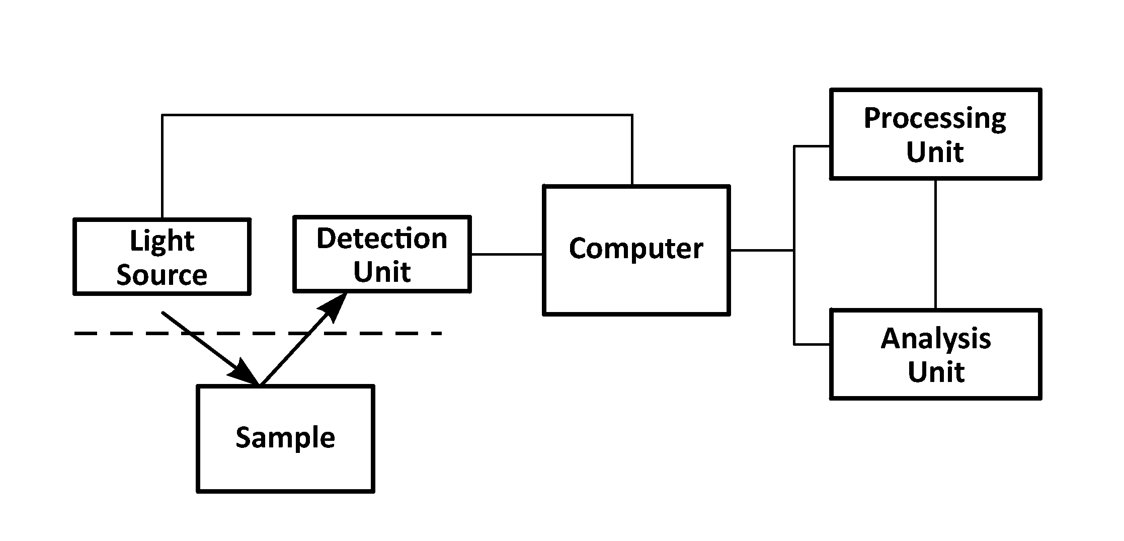
[0022]For the method of the invention, measurements at multiple detectors from more than one source position are needed. This can be done in following ways:

[0023]If x source positions are needed, the source has to be scanned through the sample in x different locations. This can be made by different approaches:[0024](A) Arrange x separate laser sources in such a way to illuminate on the x different scanning locations we need to have. Now switch ON each of the x lasers one at a time and record the corresponding measurements.[0025](B) Use only one laser source but couple this laser light into x different optical fibres and arrange each of the optical fibres in x different scanning locations on the sample. The laser light must come out from one fibre at a time; for this an optical switch can be used. By controlling the optical switch the laser source can be coupled to each fibre one at a time.[0026](C) Use only one laser source, employing a galvo mirror arrangement controlled by a compu...


PUM


Abstract

Speckle contrast optical tomography system provided with at least one point source and multiple detectors, means for providing different source positions, the point source having a coherence length of at least the source position-detector distance and means for arranging the source position-detector pairs over a sample to be inspected, the system being further provided with means for measuring the speckle contrast; the speckle contrast system of the invention thus capable of obtaining 3D images.

Description

BACKGROUND OF THE INVENTION[0001]The present invention is related to subsurface tissue blood flow imaging techniques. More particularly, the invention is based on a new highly efficient technique based on coherent laser light speckle contrast (SC) and diffuse correlation tomography.[0002]Imaging blood flow is critical to the diagnosis and monitoring of many diseases. Examples include most obviously the imaging of cerebral blood flow (CBF) for stroke and other ischemic injuries—all hemodynamic derangements—and also neurodegenerative diseases such as Alzheimer's.[0003]Coherence optical measures have traditionally had a role in rodent stroke studies by way of the laser Doppler flowmetry point measurement technique. Areas of high blood flow increase the Doppler broadening of coherent laser light. However, laser Doppler methods are point measures that rely on single scattering with limited depth penetration (<1 mm). Laser Doppler methods can be extended to imaging by raster scanning t...

Claims


Application Information

Patent Timeline
Patent Type & Authority Applications(United States)
IPC IPC(8): A61B5/026A61B5/00G01B9/02
CPCA61B5/0261A61B5/0073G01B9/02094A61B5/0062A61B5/0066A61B5/7203
Inventor DURDURAN, TURGUTVALDES, CLAUDIAKRISTOFFERSEN, ANNAVARMA, HARI M.CULVER, JOSEPH
Owner WASHINGTON UNIV IN SAINT LOUIS
Why Eureka
Try Eureka