Radar apparatus and method of determining sign of velocity

Active Publication Date: 2015-07-02
TOYOTA CENT RES & DEV LAB INC
View PDF6 Cites 113 Cited by
  • Summary
  • Abstract
  • Description
  • Claims
  • Application Information

AI Technical Summary

Benefits of technology

[0018]According to the present invention, the sign of velocity of an object can be determined simply at low cost. Since

Problems solved by technology

Hover, since AOM is expensive, there has been a problem in that such a radar apparatus entails high cost.
Also, since AOM utilizes

Method used


Image

  • Radar apparatus and method of determining sign of velocity
  • Radar apparatus and method of determining sign of velocity
  • Radar apparatus and method of determining sign of velocity

Examples


first embodiment

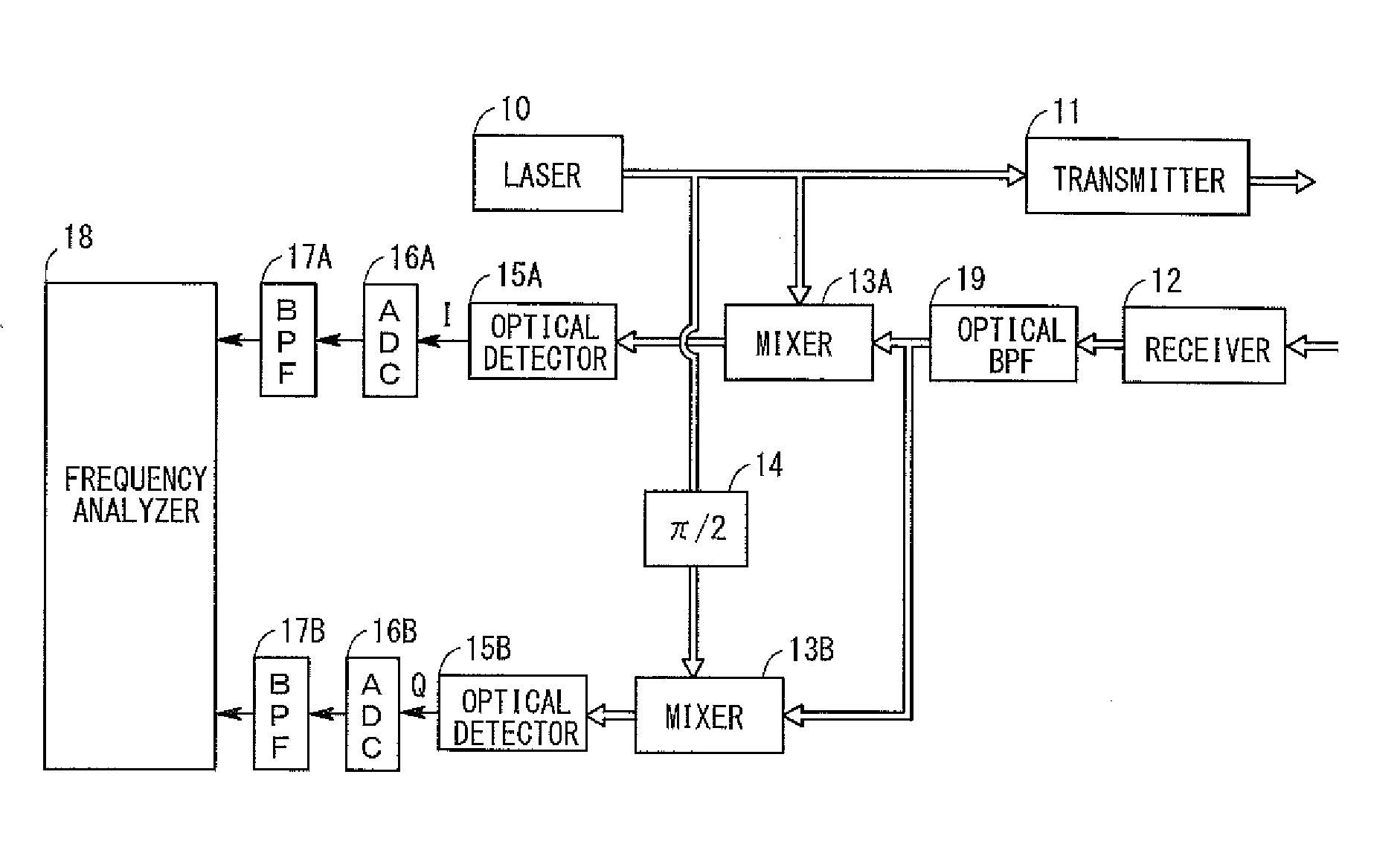
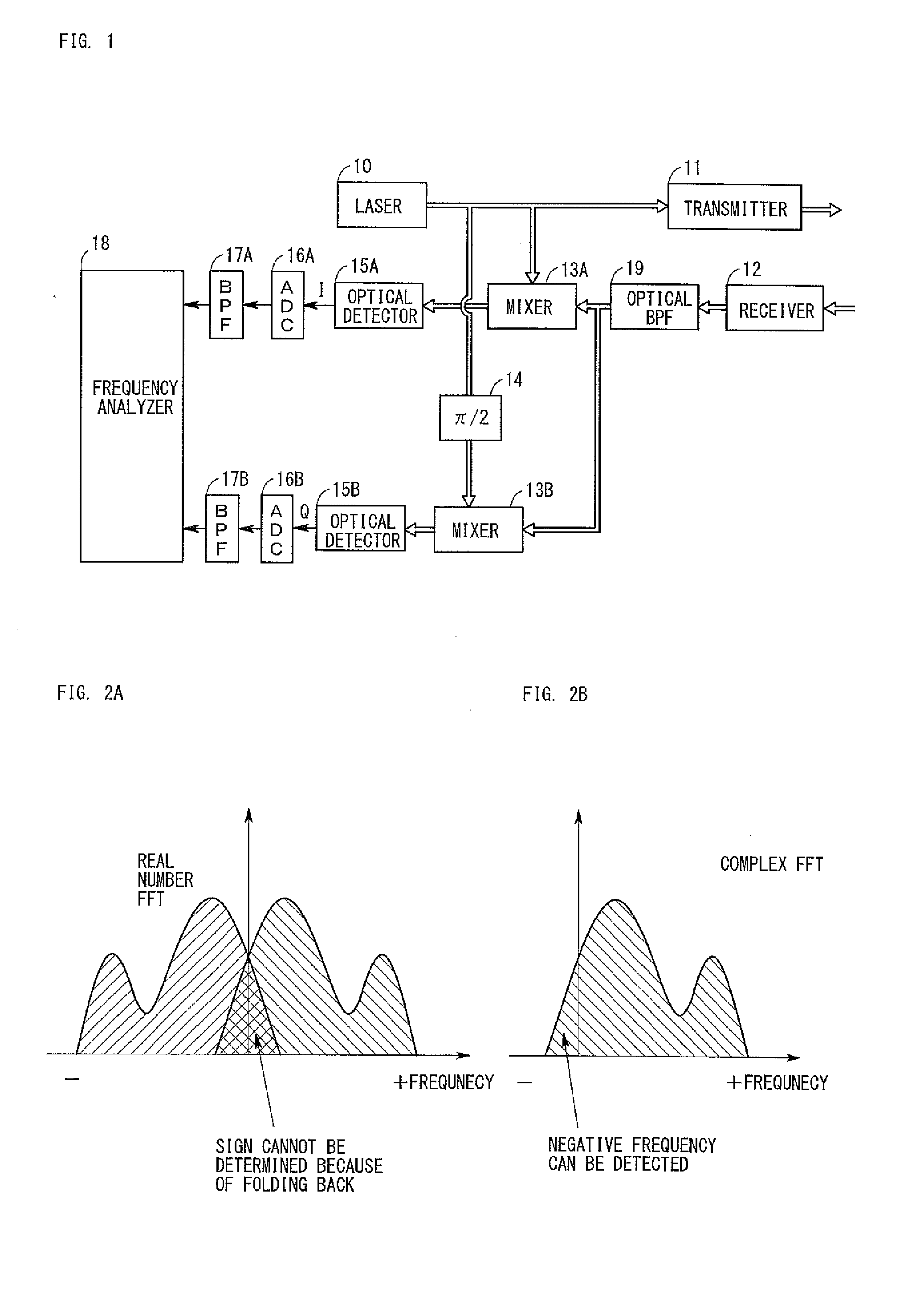
[0026]FIG. 1 is a diagram showing the configuration of a radar apparatus according to a first embodiment. In FIG. 1, arrowed double lines show paths for laser light, and arrowed single lines show paths for electric signals. As shown in FIG. 1, the radar apparatus of the first embodiment is composed of a laser 10, transmitter 11, receiver 12, mixers (couplers, hereinafter the same) 13A and 13B, a π / 2 phase shifter 14, optical detectors 15A and 15B, ADCs (analog-to-digital conversion circuits) 16A and 16B, BPFs (band-pass filters) 17A and 17B, and frequency analyzer 18. Below, these components will be described in detail.

[0027]The laser 10 radiates laser light which is continuous light having a wavelength of 1550 nm. The laser light output from the laser 10 is split into two light beams, one of which is input to a mixer 13A and the other of which is input to the π / 2 phase shifter 14.

[0028]Although the wavelength of the laser light is not limited to 1550 nm, it is desired that the wave...

second embodiment

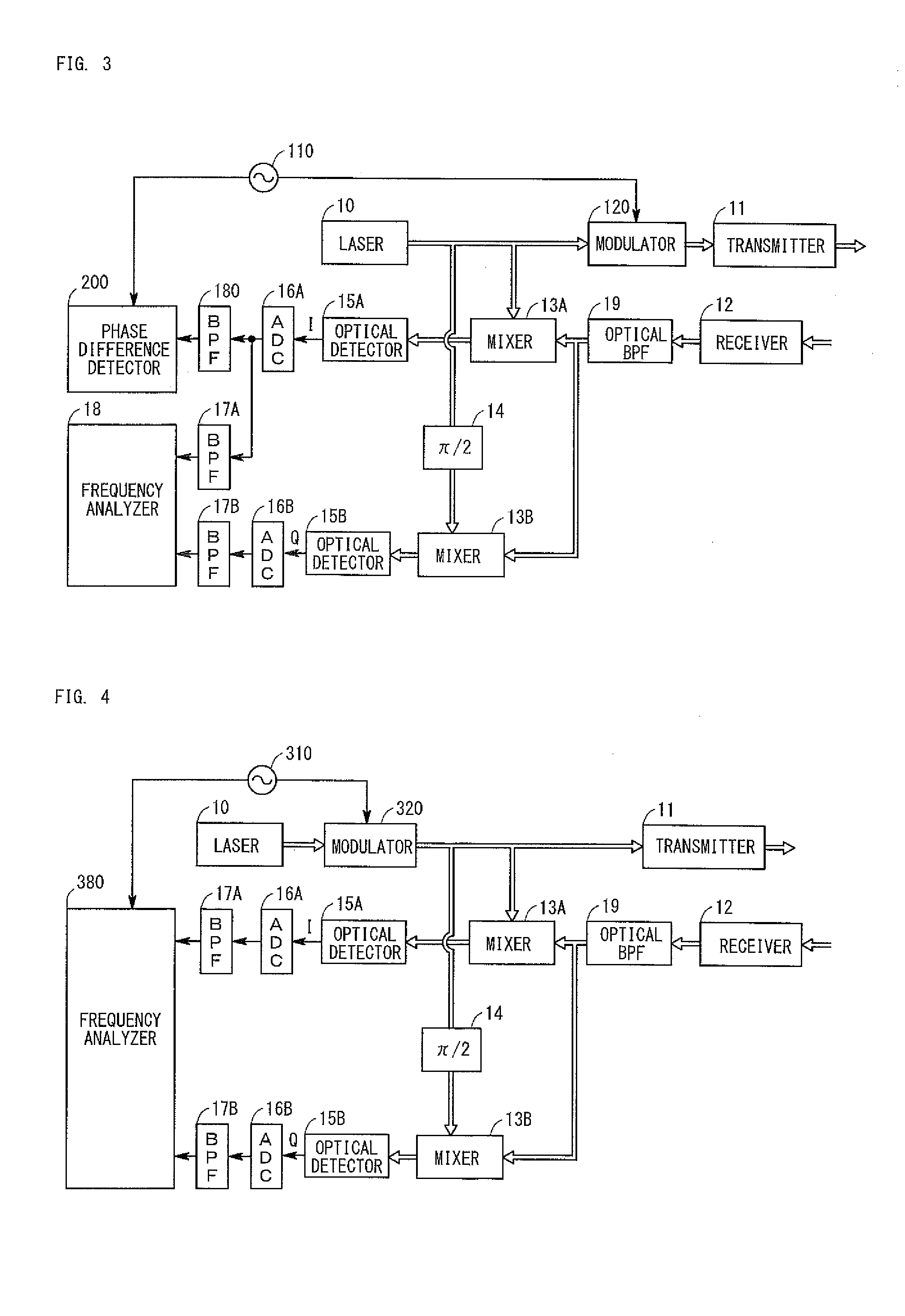
[0046]FIG. 3 is a diagram showing the configuration of a radar apparatus according to a second embodiment. The radar apparatus of the second embodiment is realized by adding the following components to the radar apparatus of the first embodiment.

[0047]As shown in FIG. 3, the radar apparatus of the second embodiment differs from the radar apparatus of the first embodiment in that an oscillator 110, a modulator 120, a BPF 180, and phase difference detector 200 are added so as to measure the distance between the radar apparatus and an object in addition to the velocity of the object. In the below, components different from those of the first embodiment will be described, and operation of the radar apparatus of the second embodiment will be described.

[0048]The oscillator 110 generates a periodic signal which is a cosine wave having a frequency of 100 kHz. This periodic signal is input to the modulator 120 and the phase difference detector 200.

[0049]The periodic signal output from the os...

third embodiment

[0062]FIG. 4 is a diagram showing the configuration of a radar apparatus according to a third embodiment. The radar apparatus of the third embodiment differs from the radar apparatus of the first embodiment in that an oscillator 310 and a modulator 320 are added, and a frequency analyzer 380 is provided in place of the frequency analyzer 18. In the below, components different from those of the first embodiment will be described, and operation of the radar apparatus of the third embodiment will be described.

[0063]The oscillator 310 generates and outputs a triangular wave whose period is T. The modulator 320 frequency-modulates the laser light on the basis of the triangular wave from the oscillator 310, and outputs the modulated laser light. As a result, the frequency of the frequency-modulated laser light changes from the center frequency f0 (1550 nm) by Δf in accordance with the triangular wave whose period is T. The laser light output from the modulator 320 is distributed and is in...


PUM


Abstract

A radar apparatus which can simply determine the sign of velocity of an object is provided. Laser light reflected by the object undergoes quadrature optical heterodyne detection performed by mixers, optical detectors, and a π/2 phase shifter, whereby I and Q component signals are output. A frequency analyzer performs FFT on a complex signal composed of the I component signal (real part) and the Q component signal (imaginary part) to thereby obtain its frequency spectrum. Since the frequency spectrum is calculated without being folded back even in a region where the frequency is negative, the sign of the Doppler frequency fd can be determined. When the Doppler frequency fd is positive, the sign of the velocity of the object is a direction toward the radar apparatus. When the Doppler frequency fd is negative, the sign of the velocity of the object is a direction away from the radar apparatus.

Description

BACKGROUND OF THE INVENTION[0001]1. Field of the Invention[0002]The present invention relates to a radar apparatus which radiates laser light toward an object, detects the laser light reflected from the object, and measures or determines the sign of velocity of the object.[0003]The term “velocity” used herein is scalar and refers to the magnitude of an orthogonal projection vector obtained by projecting a relative velocity vector of an object to the radar apparatus onto the optical axis of laser light. Therefore, the direction in which the object is present can be determined by the direction of a laser beam, and the magnitude of the orthogonal projection vector is the velocity.[0004]2. Background Art[0005]There has been conventionally known a radar apparatus (LIDAR) which emits laser light toward an object, and receives and analyzes the laser light reflected from the object, to thereby measure the distance and velocity of the object.[0006]Use of such a radar apparatus in vehicles ha...

Claims


Application Information

Patent Timeline
IPC IPC(8): G01P3/36G01S17/08
CPCG01S17/08G01P3/36G01P3/68G01S17/36G01S17/58G01S7/4917
Inventor INOUE, DAISUKEYAMASHITA, TATSUYAICHIKAWA, TADASHIKATO, SATORUHASEGAWA, KAZUO
Owner TOYOTA CENT RES & DEV LAB INC
Why Eureka
Try Eureka