Wire Stitch Bond Having Strengthened Heel

a technology of wire stitch and heel, which is applied in the direction of soldering apparatus, welding devices, manufacturing tools, etc., can solve the problems of cte mismatch exerting pulling force on the wire stitch, the heel breakage is eliminated, and the capillary maintenance is careful, the effect of optimizing machine parameters

Inactive Publication Date: 2015-07-02
TEXAS INSTR INC
View PDF1 Cites 24 Cited by
  • Summary
  • Abstract
  • Description
  • Claims
  • Application Information

AI Technical Summary

Benefits of technology

[0008]Attempts to eliminate the heel breakage by changing the encapsulation compound, optimizing the machine parameters, and careful capillary maintenance had only limited success. By tweaking the CTE of the encapsulation compound, the stress caused by CTE mismatch to the wire metal can be somewhat reduced. The machine parameters such as force, power, and time of bonding, loop height, and temperature at bonding can be varied within narrow limits to reduce stress at the bond heel. Capillary maintenance may aim at controlling bond tool life to minimize the stress on bond heel due to residue build-up.
[0009]Applicant substantially solved the heel breakage problem when he discovered that additional wire metal intentionally accumulated right in the heel during the process of wire stitch formation will fortify

Problems solved by technology

Analyzing large numbers of wire stitch bonds which failed in bond pull tests of quality and reliability investigations of wire-bonded semiconductor devices, applicant found that the majority of the failures showed as symptom wires broken at the heel of the stitch bonds.
In addition, there is thermo-mechanical stress caused by the mismatch of the coefficients of thermal e

Method used


Image

  • Wire Stitch Bond Having Strengthened Heel
  • Wire Stitch Bond Having Strengthened Heel
  • Wire Stitch Bond Having Strengthened Heel

Examples


Embodiment Construction

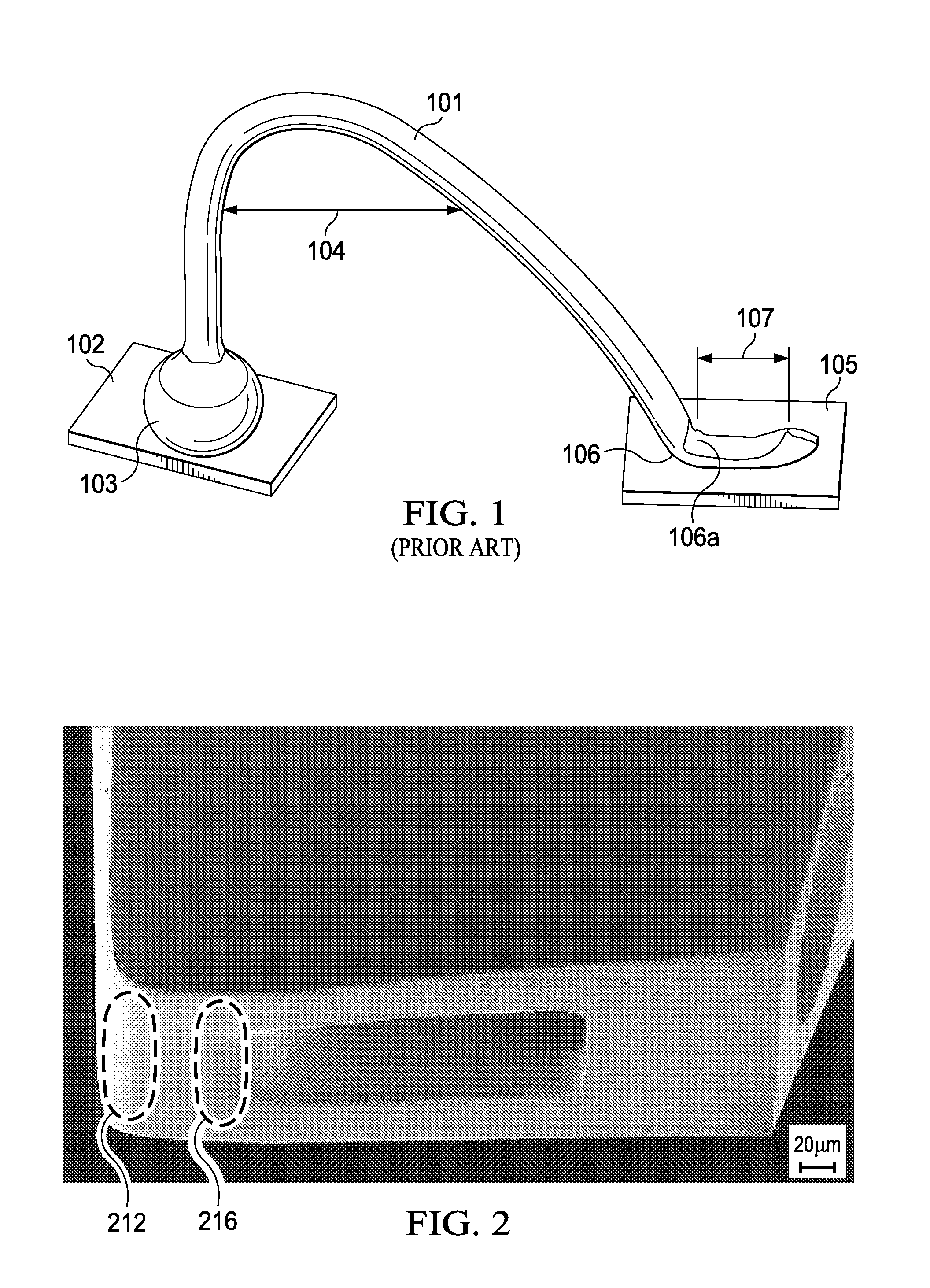
[0031]FIG. 2 illustrates a scanning electron microscope photograph (magnification 600×) of the tip, or end, of an exemplary straight tube made of an inert material such as tungsten carbide, which is preferably used in automated bonders for fabricating electrical wire connections in semiconductor devices. The tube has a certain length and inside a cylindrical bore with a very small diameter. The tube is, as a capillary tube, commonly referred to as the capillaries, or short the capillary, of wire bonders. Exemplary bores have diameters suitable to guide round metal wires with a diameter in the range from about 15 μm to 35 μm; the wires for semiconductor devices may be made of copper, gold, aluminum, or alloys of these metals. The region where the capillary bore exits the tube, is herein referred to as the capillary mouth. The perspective view of FIG. 2 shows that the mouth of the capillary bore at the tube end is elongated.

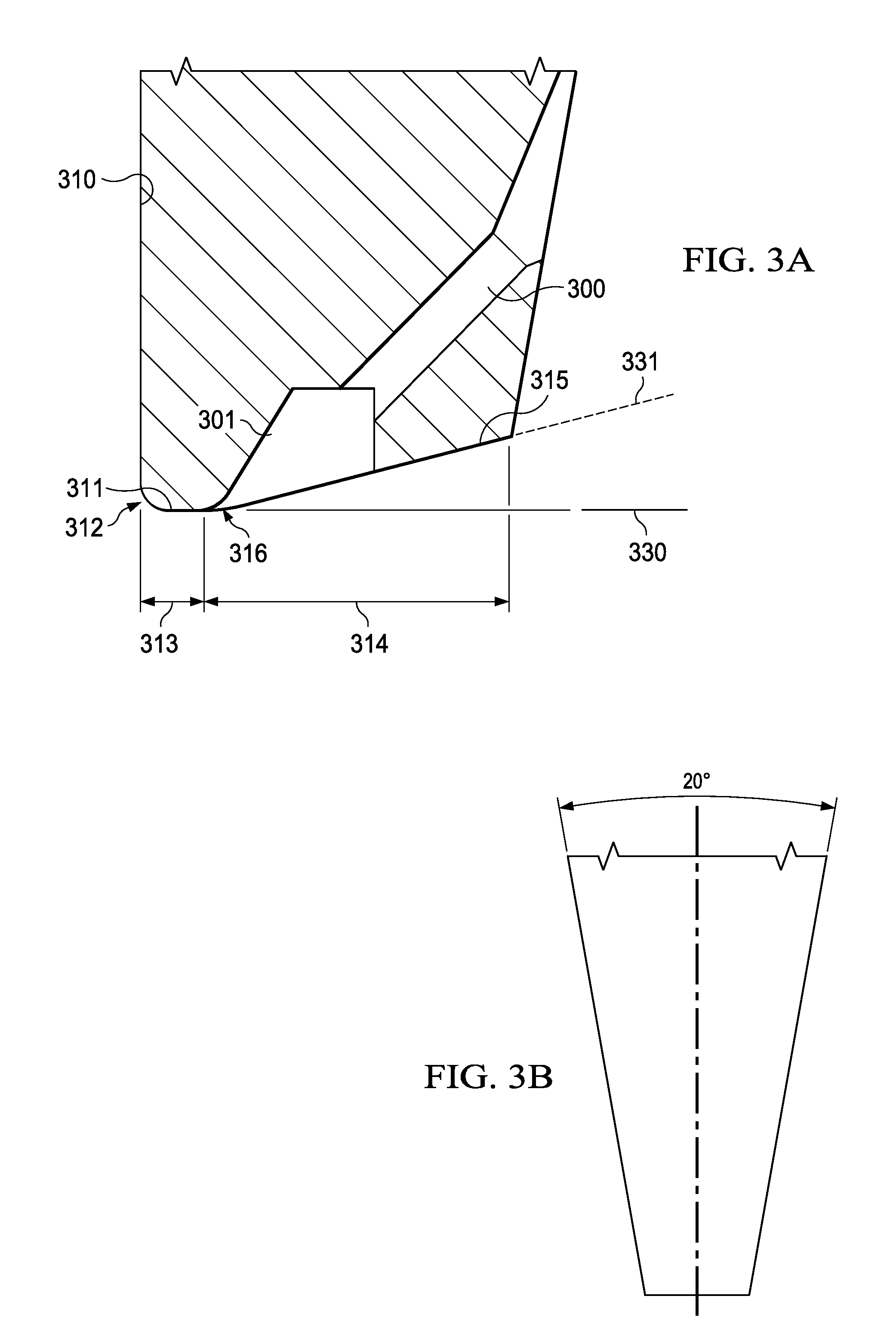
[0032]FIG. 3A is a cross section of the end portion of the ca...


PUM

PropertyMeasurementUnit
Lengthaaaaaaaaaa
Pressureaaaaaaaaaa
Sizeaaaaaaaaaa

Abstract

A semiconductor chip (1100) assembled on a substrate (1110), the chip having bond pads (1102) and the substrate having contact pads (1111). Wires (1101) form arches to connect electrically the chip and the substrate, the wires forming first bonds (1103, e.g. ball bonds) on the chip bond pads and second bonds (1107, e.g. stitch bonds) on the substrate contact pads. The second (stitch) bonds have bendings (heels) 1106 with metal bulges (1106a) near the vertex of the bending.

Description

FIELD OF THE INVENTION[0001]The present invention is related in general to the field of semiconductor devices and processes, and more specifically to the structure of wire stitch bonds and the process and tools of fabricating reliable stitch bonds.DESCRIPTION OF RELATED ART[0002]In semiconductor industry, traditionally the most widely used technology for electrically interconnecting chip terminals to external pads is wire bonding, especially ball bonding, as indicated in FIG. 1. Typically, the wires 111, made of gold, copper, or aluminum, have diameters between about 15 and 33 μm. A routine wire bonding process may begin with positioning the semiconductor chip on a heated pedestal to raise the temperature to between 150 and 300° C. For copper and aluminum wires, ball formation and bonding may need to be performed in a reducing atmosphere such as dry nitrogen gas with a few percent hydrogen gas. The wire is strung through the capillary of an automated bonder. A capillary is an elonga...

Claims


Application Information

Patent Timeline
IPC IPC(8): H01L23/00
CPCH01L24/85H01L24/78H01L2224/85345H01L2224/85205H01L24/49H01L24/45H01L24/48H01L2224/05553H01L2224/05639H01L2224/05647H01L2224/45015H01L2224/45124H01L2224/45144H01L2224/45147H01L2224/48091H01L2224/48247H01L2224/48456H01L2224/48465H01L2224/48472H01L2224/48639H01L2224/48647H01L2224/48839H01L2224/48847H01L2224/49175H01L2224/78313H01L2224/78315H01L2924/3512H01L2924/00014H01L2924/20751H01L2924/20752H01L2924/20753H01L2924/00015H01L2924/00H01L2924/00012
Inventor CHEW, JIUN WAI
Owner TEXAS INSTR INC
Why Eureka
Try Eureka