Error correction encoding method and error correction encoding device

a technology of error correction and encoding method, which is applied in the direction of coding, code conversion, electrical apparatus, etc., can solve the problems of large computation amount and large number of exclusive or exclusive times, and achieve the reduction of reducing computation amount for encoding qc-ldpc codes

Active Publication Date: 2015-07-02
MITSUBISHI ELECTRIC CORP
View PDF2 Cites 9 Cited by
  • Summary
  • Abstract
  • Description
  • Claims
  • Application Information

AI Technical Summary

Benefits of technology

[0018]Because the error correction encoding method according to the present invention performs the multiplication of the parity-check matrix and the information bit sequence while dividing the multiplication into two steps, the size of the matrix which is multiplied by the vector in the matrix multiplying step and is not sparse can be reduced to less than that in the conventional method. Therefore, the amount of computations for the encoding of an LDPC code can be reduced.
[0019]Because the error correction encoding method according to the present invention performs the multiplication of the parity-check matrix and the information bit sequence while dividing the multiplication into plural steps, the size of the matrix which is multiplied by the vector in the matrix multiplying step and is not sparse can be reduced to less than that in the conventional method and many of the computations can be performed by using sparse matrices. Therefore, the amount of computations for the encoding of a QC (Quasi-Cyclic)-LDPC code can be reduced.
[0020]Because the error correction encoding method according to the present invention uses the equations (24), (26), and (27), which will be mentioned below, many

Problems solved by technology

Therefore, a problem is that the number of times of exclusive OR is large and the amount of computations

Method used


Image

  • Error correction encoding method and error correction encoding device
  • Error correction encoding method and error correction encoding device
  • Error correction encoding method and error correction encoding device

Examples


embodiment 1

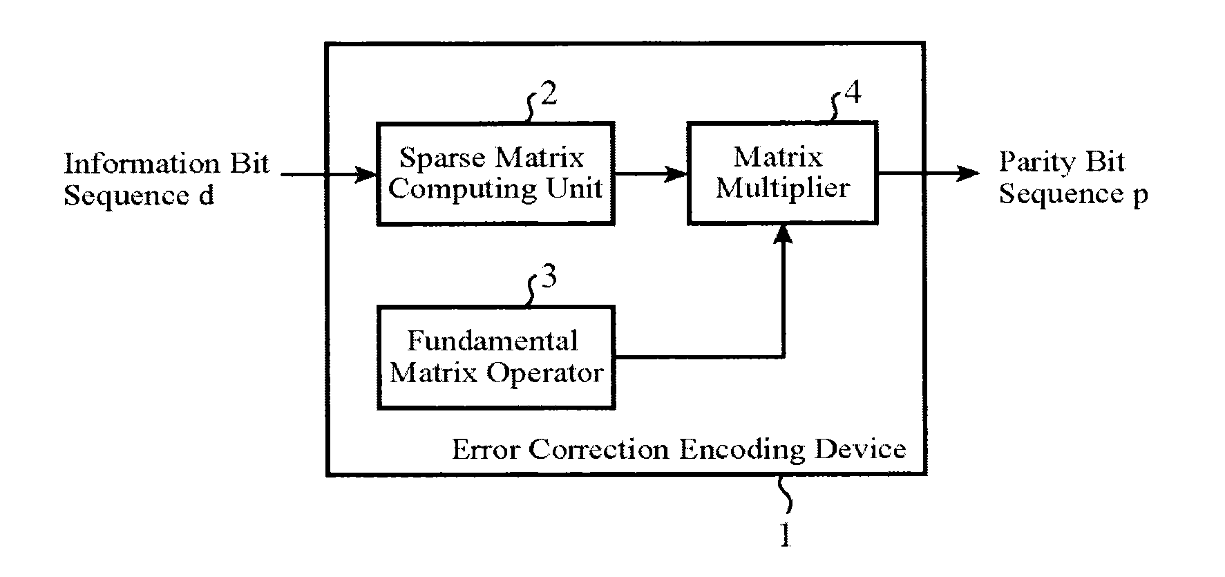
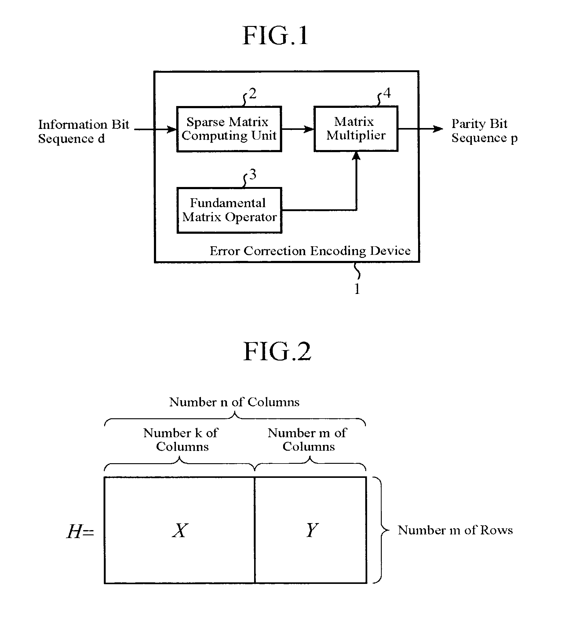
[0039]An error correction encoding device 1 shown in FIG. 1 is provided with a sparse matrix computing unit 2, a fundamental matrix operator 3, and a matrix multiplier 4. As encoding of an LDPC code, the error correction encoding device receives an information bit sequence d as its input, and calculates a parity bit sequence p which satisfies a condition based on a parity-check matrix H.

[0040]There is a relationship, as shown in equation (4), between the parity-check matrix H for LDPC codes and a codeword c.

HcT=(0, . . . ,0)T  (4)

[0041]Hereafter, it is assumed that an addition of elements (bits) which is performed in a multiplication of the matrix H and the vector c is an addition using modulo 2 (which is the same as exclusive OR). Further, T shows a transposition.

[0042]The parity-check matrix H is expressed as shown in equation (5) and FIG. 2. This parity-check matrix H includes an m×k matrix X corresponding to the information bit sequence d, and an m×m matrix Y corresponding to th...

embodiment 2

[0052]FIG. 4 is a block diagram showing the structure of an error correction encoding device 1 in accordance with this Embodiment 2. The error correction encoding device 1 in accordance with this Embodiment 2 is provided with a sparse matrix computing unit 2, a fundamental matrix operator 3, a matrix multiplier 4, and a parity bit calculator 5. In FIG. 4, the same components as those shown in FIG. 1 or like components are designated by the same reference numerals, and the explanation of the components will be omitted hereafter.

[0053]Although the error correction encoding method in the case in which the above equation (4) is deformed into the above equation (7) is explained in above-mentioned Embodiment 1, an error correction encoding method in the case in which the above equation (4) is deformed into equation (8) shown below will be explained in Embodiment 2.

XdT+YpT=0

YpT=−XdT

T1pT=SXdT  (8)

[0054]A matrix T1 in the equation (8) is an m×m matrix, and is a lower triangular matrix as sh...

embodiment 3

[0076]In this Embodiment 3, QC-LDPC codes are handled. A QC-LDPC code is a type of LDPC code, and is an LDPC code in which a parity-check matrix is constructed of blocks each of which is a circulant permutation matrix.

[0077]An example of a QC-LDPC code is shown in equation (15). In the equation (15), the number n of columns of the parity-check matrix H is set to n=Nq, and the number of rows of the matrix is set to m=Mq. More specifically, the parity-check matrix H has a structure of including M (Xij, Yij) with respect to a vertical direction and N (Xij, Yij) with respect to a horizontal direction. Further, the following relationship: K=N−M is established.

[0078]In addition, in the equation (15), the element Xij at the i-th row and the j-th column (1≦i≦M, 1≦j≦K) and the element Yij at the i-th row and the j-th column (1≦i≦M, 1≦j≦M) are q×q square matrices, respectively, and each of them is a circulant permutation matrix or a zero matrix. A circulant permutation matrix is the one in wh...


PUM


Abstract

An error correction encoding device 1 includes a sparse matrix computing unit 2 that computes exclusive OR of a submatrix, in a parity-check matrix, corresponding to an information bit sequence, and the information bit sequence on the basis of the position of 1 in the submatrix to calculate a vector, a fundamental matrix operator 3 that calculates a predetermined matrix by performing a predetermined fundamental matrix operation on a submatrix, in the parity-check matrix, corresponding to a parity bit sequence, and a matrix multiplier 4 that calculates the parity bit sequence by multiplying the predetermined matrix which the fundamental matrix operator 3 calculates, and the vector which the sparse matrix computing unit 2 calculates.

Description

FIELD OF THE INVENTION[0001]The present invention relates to an error correction encoding method and an error correction encoding device that perform encoding according to Low-Density Parity-Check codes (referred to as LDPC codes from here on).BACKGROUND OF THE INVENTION[0002]Error correcting codes are a technique of correcting an error bit which is caused by noise occurring in a communication channel in a communication system. In a communication system using this technique, instead of transmitting information data from a transmitter, just as they are, a process, which is referred to as encoding, is performed on an information bit sequence d (equation 1) to be transmitted to calculate a parity bit sequence p (equation 2), and a codeword c (equation 3) which is a sequence which is a combination of the information bit sequence d and the parity bit sequence p is transmitted.d=(d1,d2, . . . ,dk)  (1)p=(p1,p2, . . . ,pm)  (2)c=(d1,d2, . . . ,d1,p1,p2, . . . ,pm)  (3)[0003]Although the tr...

Claims


Application Information

Patent Timeline
IPC IPC(8): H03M13/00H03M13/11
CPCH03M13/1177H03M13/616H03M13/116H03M13/118H03M13/1185H03M13/611
Inventor SUGIHARA, KENYAMATSUMOTO, WATARU
Owner MITSUBISHI ELECTRIC CORP
Why Eureka
Try Eureka