Apparatus for corneal shape analysis and method for determining a corneal thickness

a technology of corneal shape and apparatus, which is applied in the field of apparatus for corneal shape analysis and method for determining corneal thickness, can solve the problems of affecting the accuracy of the captured image,

a technology of corneal shape and apparatus, which is applied in the field of apparatus for corneal shape analysis and method for determining corneal thickness, can solve the problems of affecting the accuracy of the captured image,

US20150190046A1Active Publication Date: 2015-07-09CASSINI TECH BV

Image

  • Apparatus for corneal shape analysis and method for determining a corneal thickness
  • Apparatus for corneal shape analysis and method for determining a corneal thickness
  • Apparatus for corneal shape analysis and method for determining a corneal thickness

Examples


Embodiment Construction

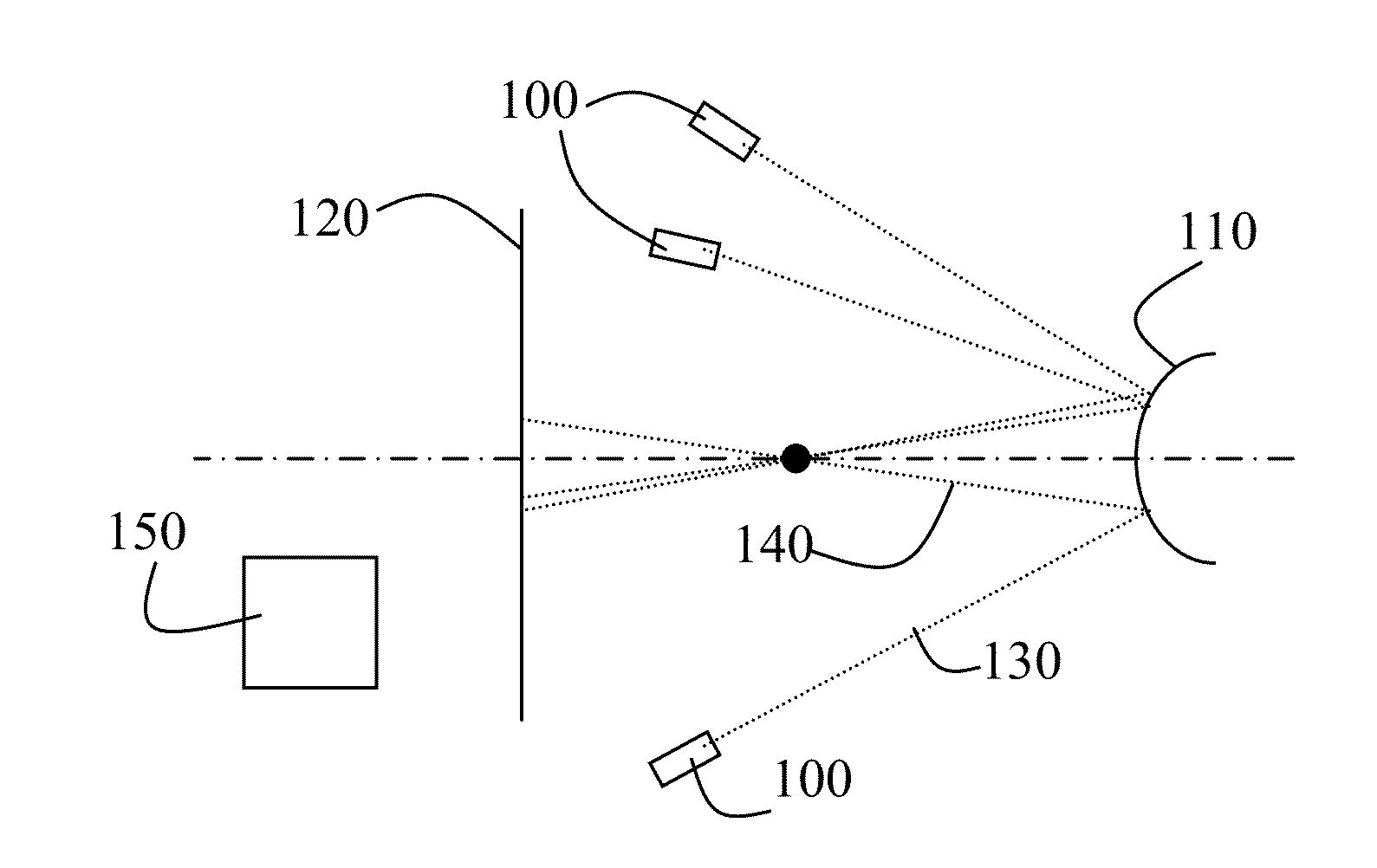
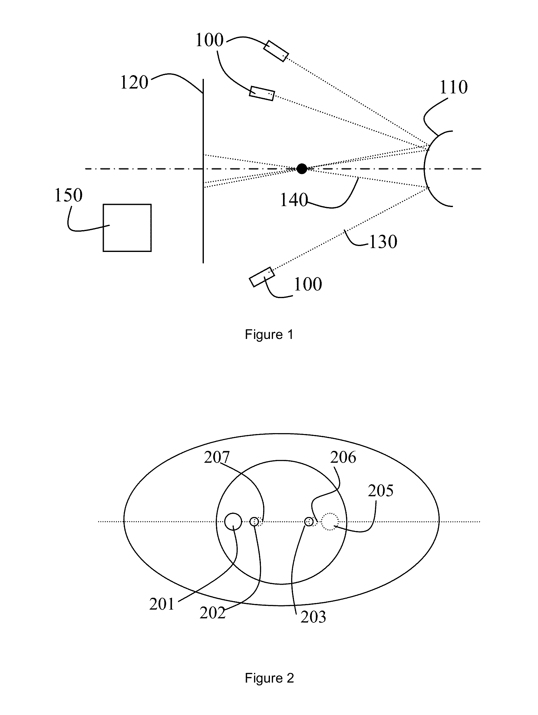
[0085]FIG. 1 schematically depicts a first embodiment of an apparatus for corneal diagnosis according to the disclosure. The apparatus comprises a plurality of stimulator point light sources 100 arranged to, in use, illuminate a cornea of an eye. Contour 110 schematically represent the anterior surface of the cornea. The apparatus further comprises a camera system 120 arranged to capture an image of the reflections of the stimulator point light sources on the cornea. FIG. 1 further schematically depicts rays of light 130 originating from the plurality of stimulator point light sources and directed towards the cornea and the corresponding reflected rays 140 on the anterior surface 110 of the cornea. The apparatus as shown in FIG. 1 further comprises a computation unit 150 arranged to process an image obtained from the camera system in such manner that a corneal thickness is obtained.

[0086]In accordance with the present disclosure, a computational unit 150 may e.g. comprise a processo...


PUM


Abstract

A method of determining a corneal thickness and an apparatus for determining the same. The method comprises the following steps of illuminating a cornea by a plurality of stimulator point light sources, capturing an image of the cornea comprising reflected images of the stimulator point light sources, obtaining a first model representing an anterior surface of the cornea, constructing a second model representing a posterior surface of the cornea from the image by ray-tracing the reflected images of the stimulator point light sources towards the first model representing the anterior surface of the cornea, and determining the corneal thickness from the first model representing the anterior surface and the second model representing the posterior surface.

Description

CROSS-REFERENCE TO RELATED APPLICATIONS[0001]This application claim priority benefit under 35 U.S.C. §120 as a Continuation-in-Part of prior non-provisional U.S. Utility patent application Ser. No. 12 / 937,816, filed 14 Oct. 2010, now allowed, entitled APPARATUS FOR CORNEAL SHAPE ANALYSIS AND METHOD FOR DETERMINING A CORNEAL THICKNESS, which application in turn is the National Stage under 35 U.S.C. §371 of International Application No. PCT / EP2009 / 002977, filed Apr. 16, 2009, which claims the benefit of European Application No. EP 08075303.1, filed Apr. 17, 2008. The entire contents and disclosure of these related and / or priority applications are hereby incorporated by this reference herein for all purposes.BACKGROUND OF THE DISCLOSURE[0002]Determination of a corneal thickness is important for various diagnostic applications as well as an important part of various surgical interventions on the eye. A method and apparatus for obtaining such a thickness is e.g. known from U.S. Pat. No. ...

Claims


Application Information

Patent Timeline
09 Jul 2015
Publication
US20150190046A1
IPC
A61B3/00; A61B3/10; A61B3/107; A61B19/00; A61B3/135; A61B3/117; A61B3/14
CPC
A61B3/0025; A61B3/117; A61B3/1005; A61B3/14; A61B19/5202; G02B26/0816; A61B3/135; A61B3/107
Inventors
DE PAZ SICAM, VICTOR ARNI; PIPER, ROLAND BRYN