Method and system for separating catalyst fines from an oil stream

a technology of catalyst fines and oil stream, which is applied in the direction of centrifuges, analysis using nuclear magnetic resonance, fuels, etc., can solve the problems of long term accumulation of catalyst fines on the bottom of fuel oil bunkers, difficult cleaning by conventional methods, wear of engine and auxiliary equipment, etc., to reduce the risk of engine damage and reduce the amount of catalyst fines

Inactive Publication Date: 2015-07-09
ALFA LAVAL CORP AB
View PDF3 Cites 9 Cited by
  • Summary
  • Abstract
  • Description
  • Claims
  • Application Information

AI Technical Summary

Benefits of technology

[0004]It is an object of the invention to cope with the above mentioned variations in the quality of fuel oil and to be able to minimize the amount of catalyst fines in the fuel oil in order to reduce the risk of damage on the engine.

Problems solved by technology

These particles are undesired in the fuel oil since they are abrasive and may cause wear in the engine and auxiliary equipment.
If the size distribution of the catalyst fines in the fuel oil is such that it contains a lot of smaller particles it may be difficult to clean by conventional methods.
Due to the settling there may also be a long term build-up of catalyst fines on the bottom of fuel oil bunkers.

Method used


Image

  • Method and system for separating catalyst fines from an oil stream
  • Method and system for separating catalyst fines from an oil stream

Examples


Embodiment Construction

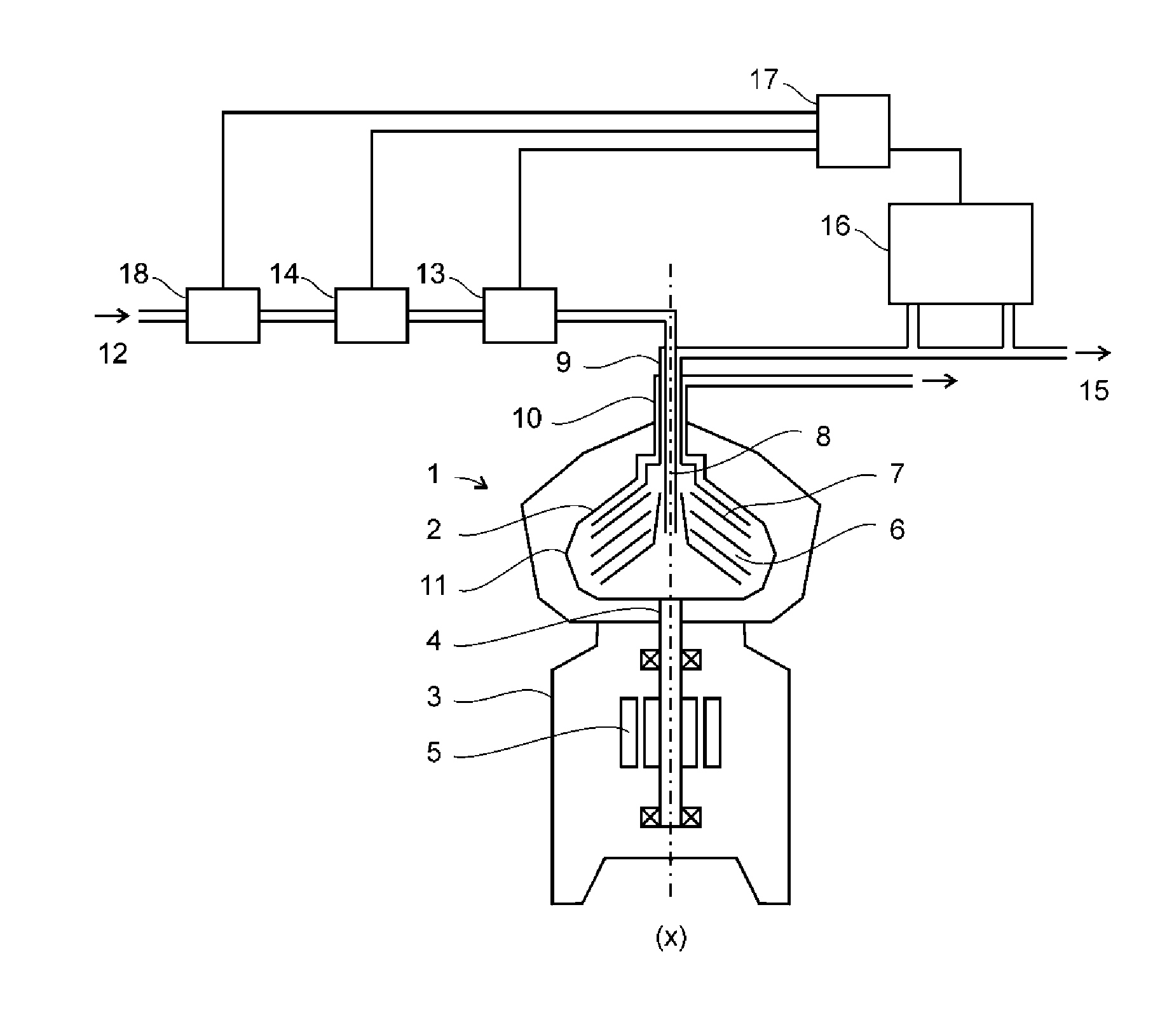
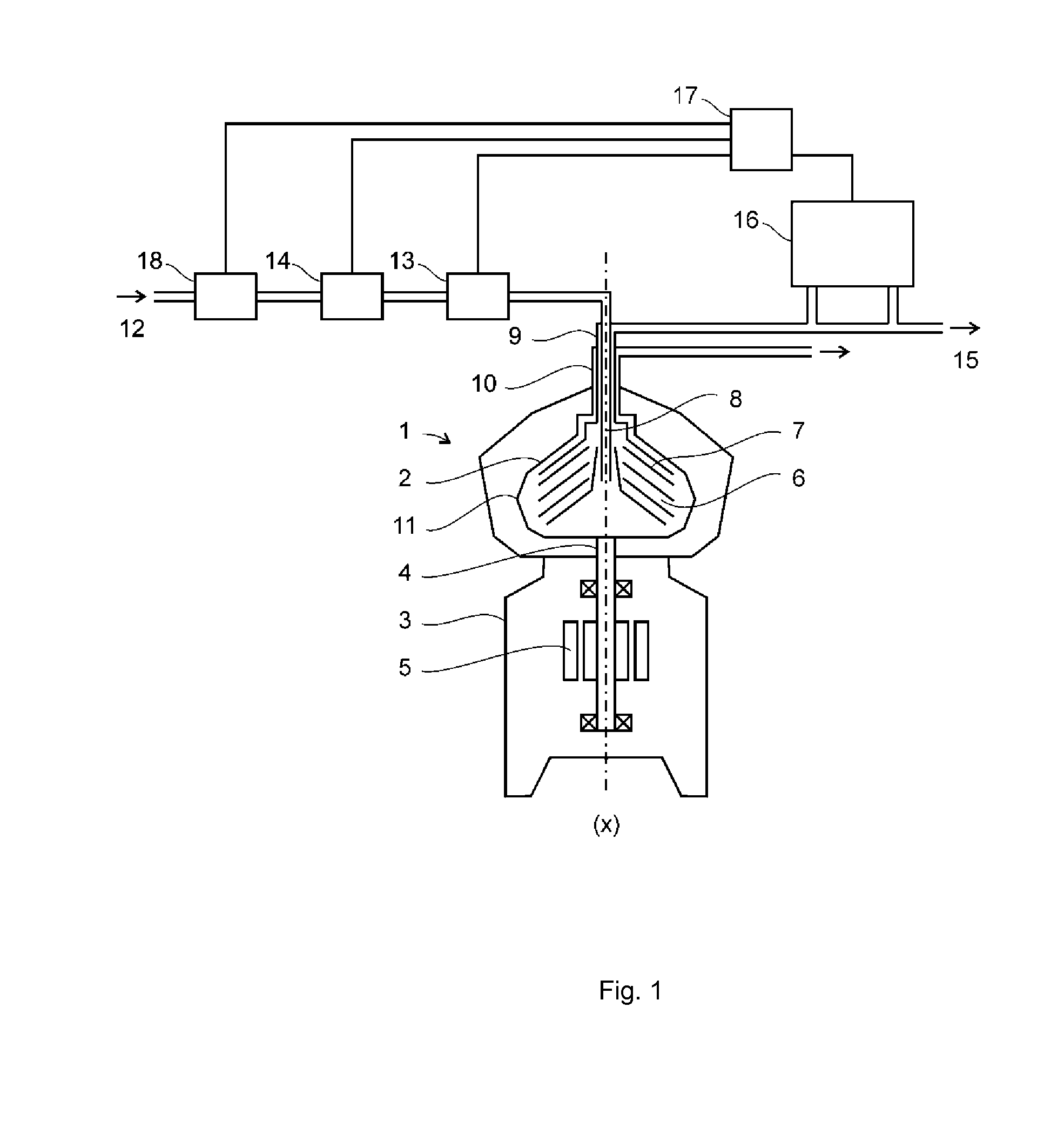
[0065]In FIG. 1 a system is shown comprising a centrifugal separator 1 for separating a liquid mixture of components, such as fuel oil contaminated with water and catalyst fines. The centrifugal separator comprises a rotor 2 supported by a spindle 4 which is rotatably arranged in a frame 3 around an axis of rotation (x). The separator comprises a drive motor 5, which may be arranged to drive the spindle in direct connection as shown or indirectly via a transmission such as belts or gears. The rotor forms within itself a separation chamber 6 wherein a stack of frustoconical separation discs 7 is arranged. An inlet 8 extends into the separation space for supply of the liquid mixture to be separated and a light phase outlet 9 for a separated light liquid component of the mixture (i.e. the purified oil) extends from the central portion of the separation chamber. A heavy phase outlet 10 for a separated heavy liquid component of the mixture (e.g. water and separation aid) extends from a p...


PUM

PropertyMeasurementUnit
molecular weightaaaaaaaaaa
temperatureaaaaaaaaaa

Abstract

The present invention relates to a method for separating catalyst fines from an oil stream comprising the steps of; separating catalyst fines from an inlet oil stream in a centrifugal separator to generate a stream of purified oil; obtaining an NMR response signal from an NMR apparatus related to the amount of catalyst fines in the purified oil stream and / or the inlet oil stream and initiating the addition of or increasing the amount of separation aid to the inlet oil stream when the NMR response signal indicates an increased amount of catalyst fines in the purified oil stream and / or the inlet oil stream, such as to increase the performance of separating catalyst fines from the oil stream.

Description

FIELD OF THE INVENTION[0001]The invention relates to a method for separating catalyst fines from an oil stream and a system comprising a centrifugal separator for separating catalyst fines from an oil stream.BACKGROUND OF THE INVENTION[0002]Fuel oil for diesel engines on board ships and in power stations contains particles of silicon and aluminium compounds (e.g. microporous aluminium silicates or aluminosilicates known as zeolites), called catalyst fines. Catalyst fines are residues from the refining process of crude oil known as catalytic cracking, wherein long hydrocarbon molecules are cracked into shorter molecules. These particles are undesired in the fuel oil since they are abrasive and may cause wear in the engine and auxiliary equipment. The concentration of catalyst fines in the fuel oil normally varies between 0 and 60 ppm. Catalyst fines are in the size range from 0.1 microns (micrometers) to 100 microns. By conventional cleaning in centrifugal separators catalyst fines d...

Claims


Application Information

Patent Timeline
Patent Type & Authority Applications(United States)
IPC IPC(8): C10G31/10C10G21/16G01N24/08B04B13/00C10M175/00C10G21/08C10L1/08
CPCC10G31/10C10G21/08C10G21/16C10L1/08C10L2290/544C10M175/0058G01N24/08C10L2270/026B04B13/00C10L2230/02C10L2250/04C10L2290/141C10L2290/54C10L2290/60
Inventor ENGLUND, MATS
Owner ALFA LAVAL CORP AB
Why Eureka
Try Eureka