

Boot seal for variable compression ratio engine
- Summary
- Abstract
- Description
- Claims
- Application Information
AI Technical Summary
Benefits of technology
Problems solved by technology
Method used
Image

Examples
first preferred embodiment
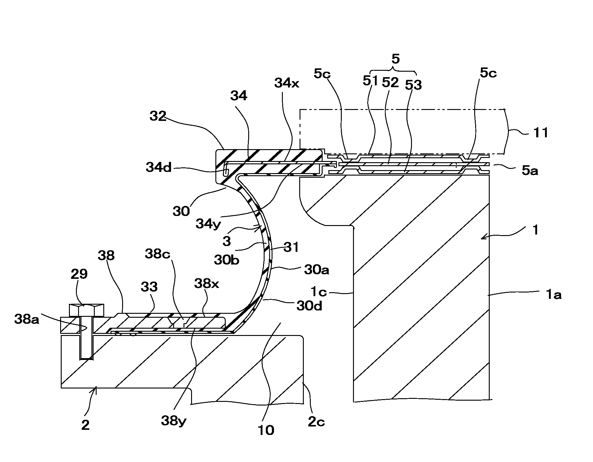
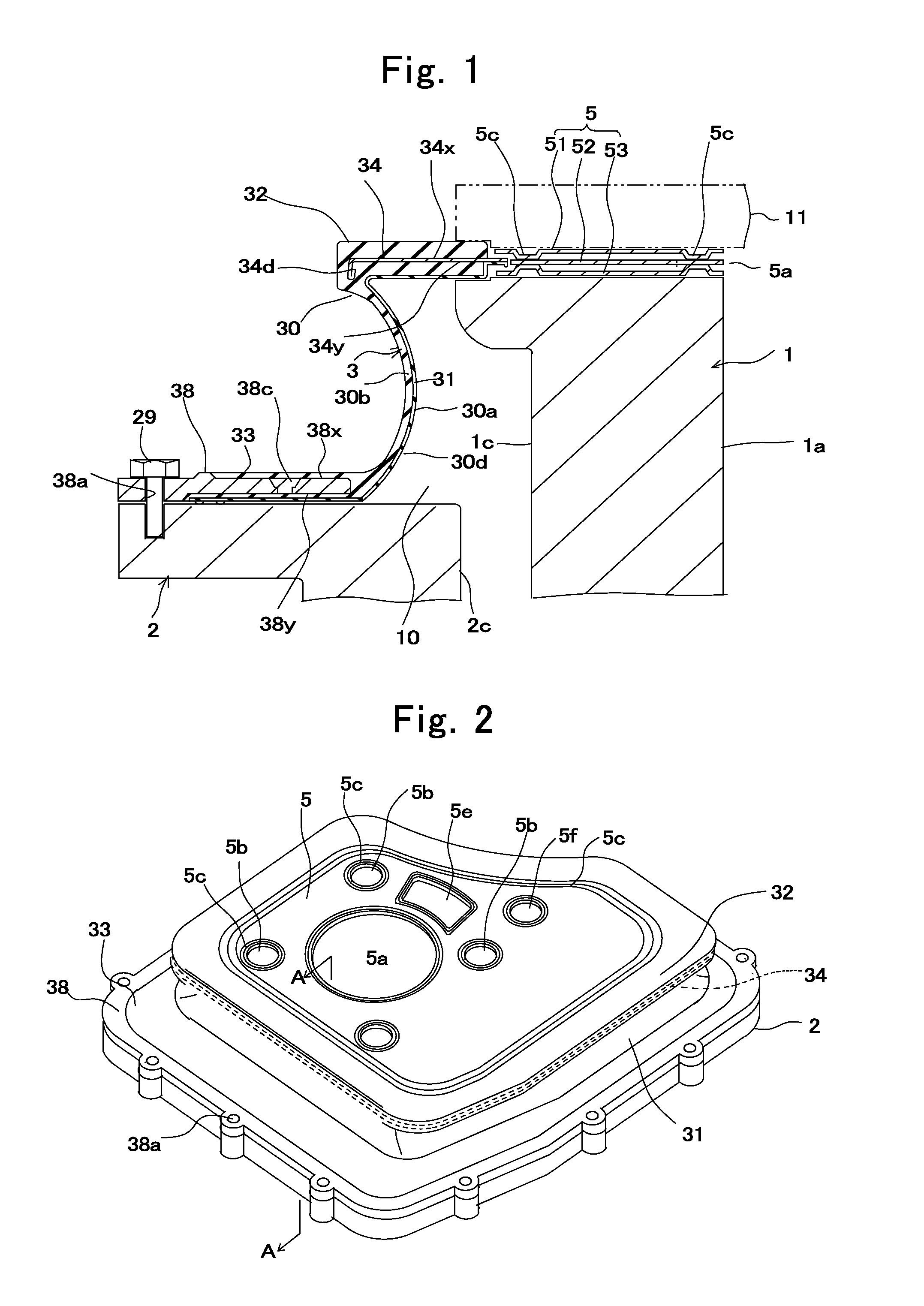
[0042]A first preferred embodiment of the present invention will be described with reference to FIGS. 1 to 9. As shown in FIG. 1, a boot seal for use with a VCR engine according to the present embodiment is a boot seal 3 attached to a VCR engine which varies the compression ratio by vertically changing relative positions of a cylinder block 1 and a crankcase 2 and covering a gap 10 between the cylinder block 1 and the crankcase 2.
[0043]The cylinder block 1 has a roughly solid rectangular parallelepiped shape and is placed in the crankcase 2 having a rough box shape. The cylinder block 1 is movable in a perpendicular direction to the crankcase 2. An outer circumferential surface 1c of the cylinder block 1 opposes an inner circumferential surface 2c of the crankcase 2 with a gap 10 therebetween. Blowby gas leaked from a combustion chamber flows in this gap 10.
[0044]As shown in FIGS. 1 and 2, the cylinder block 1 has one cylindrical part 1a. The cylindrical part 1a constitutes a cylind...
second preferred embodiment
[0086]In a boot seal of the present embodiment shown in FIG. 10, a rigid plate 34 disposed in a cylinder-attaching part 32 is integrally formed with a cylinder head gasket 5. The cylinder head gasket 5 has a three-layer structure comprising a stack of an outer metal plate 51, a middle metal plate 52 and an inner metal plate 53. The rigid plate 34 of the cylinder-attaching part 32 is integrally formed as an extension of an outer peripheral portion of the middle metal plate 52 of the cylinder head gasket 5. Other structural features of the boot seal 3 of the present embodiment are the same as those of the first preferred embodiment.
[0087]In the present embodiment, too, injection gates 82c, 82d for the outer layer 30b are located at portions of the outer layer 30b opposing the rigid plate 34 and a rigid plate 38, respectively. Since an AEM material spreads into every portion of outer surfaces 34x, 38x and inner surfaces 34y, 38y of the rigid plates 34, 38 by flowing through through hol...
third preferred embodiment
[0088]A boot seal according to the present embodiment is attached to a four-cylinder VCR engine, as shown in FIGS. 11, 12. A cylinder block of the engine has four cylindrical parts arranged in series. A cylinder head gasket 5 covering an upper portion of the engine has piston openings 5a of the same number as that of the cylindrical parts of the cylinder block, bolt holes 5b for bolting the cylinder block, the boot seal 3 and the cylinder head, water holes 5e for cylinder-surrounding components of an engine cooling system, and oil holes 5f for cylinder-surrounding components of a lubricating oil system.
[0089]The cylinder gasket 5 has a three-layer structure comprising a stack of an outer metal plate, not shown, a middle metal plate 52 and an inner metal plate, not shown. A rigid plate, not shown, of a cylinder-attaching part 32 is integrally formed as an extension of an outer peripheral portion of the middle metal plate 52 of the cylinder head gasket. Other structural features of th...
PUM
 Abstract
Description
Claims
Application Information