
Optical fiber processing system using a co2 laser

Inactive Publication Date: 2015-07-09
AFL COMM LLC
View PDF9 Cites 3 Cited by
  • Summary
  • Abstract
  • Description
  • Claims
  • Application Information

AI Technical Summary

Benefits of technology

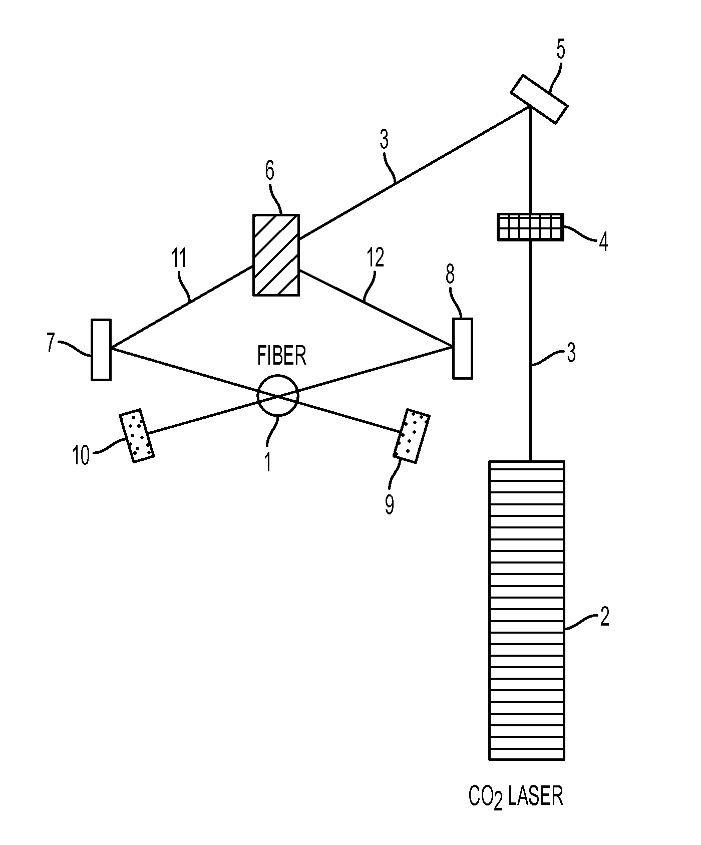
The patent is about an apparatus and method for splicing, tapering, and heat treating optical fibers. The apparatus has three or more beams that are incident on the fiber and have equal powers and directions. These beams are placed around the fiber in a way that their angles with the fiber are equal. This setup ensures uniform irradiation on the fiber's surface. The method involves using the same apparatus with three or more beams to process optical fibers. The technical effects of this invention are improved fiber processing with reduced coupling between the beams and improved irradiation uniformity on the fiber's surface.

Problems solved by technology

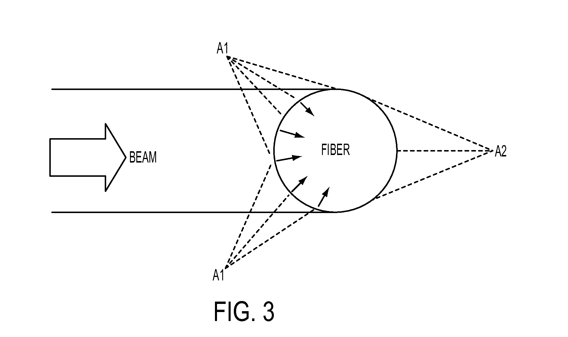
Consequently, the exterior surface of the fiber is non-uniformly heated and may have a non-uniform temperature distribution.
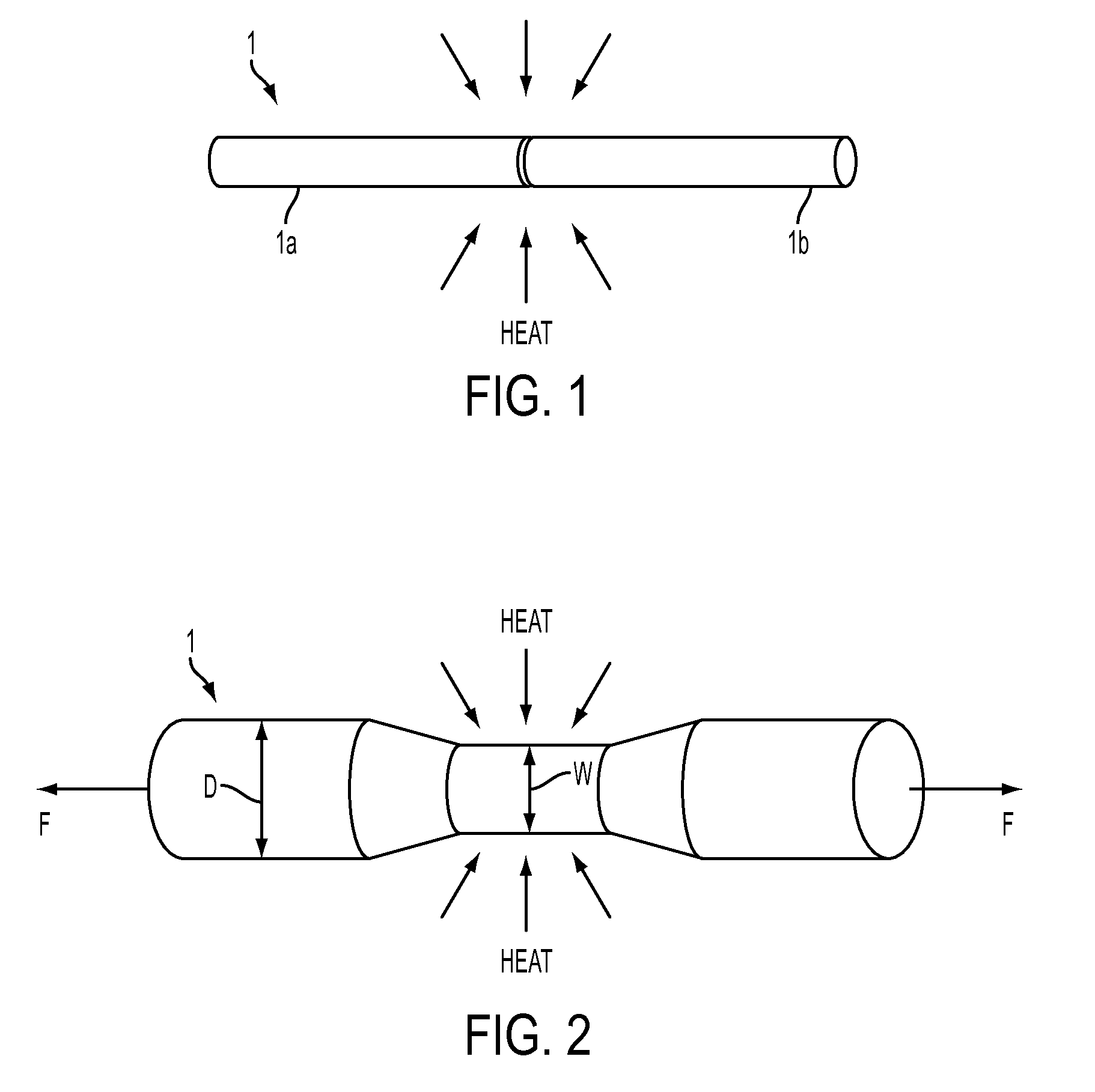
This change in shape of the fiber, due to heat processing such as splicing and tapering, is detrimental to the optical properties of the fiber and is unwanted.

Method used


Image

  • Optical fiber processing system using a co2 laser
  • Optical fiber processing system using a co2 laser
  • Optical fiber processing system using a co2 laser

Examples


Embodiment Construction

[0032]The following detailed description is provided to gain a comprehensive understanding of the methods, apparatuses and / or systems described herein. Various changes, modifications, and equivalents of the systems, apparatuses and / or methods described herein will suggest themselves to those of ordinary skill in the art. Descriptions of well-known functions and structures are omitted to enhance clarity and conciseness.

[0033]Throughout the drawings and the detailed description, unless otherwise described, the same drawing reference numerals are understood to refer to the same elements, features, and structures. The relative size and depiction of these elements may be exaggerated for clarity.

[0034]Further, it will be understood that when an element is referred to as being “connected to” another element, it can be directly connected to the other element, or intervening elements may be present. The terminology used herein is for the purpose of describing particular embodiments only and ...


PUM

PropertyMeasurementUnit
Angleaaaaaaaaaa
Poweraaaaaaaaaa
Sizeaaaaaaaaaa

Abstract

An apparatus for splicing, tapering and heat processing optical fibers is disclosed. The apparatus may include a laser configured to irradiate a portion of one or more optical fibers by at least two laser beams. The beams may be configured to irradiate different areas of the exterior surface of the fiber portion such as to increase the uniformity of heating distribution over the exterior surface of a portion of the optical fiber. In a configuration using two beams to irradiate the fiber portion the angle between the beams may be the closest angle to 180 degrees for which coupling between the first beam and the second beam is avoided. The apparatus may include three or more beams distributed around the optical fiber such as to irradiate the fiber portion uniformly and provide uniform heating of the fiber.

Description

CROSS-REFERENCE TO RELATED APPLICATIONS[0001]This application is based upon and claims the benefit of priority from U.S. Provisional Applications No. 61 / 664,969, filed Jun. 27, 2012, and Provisional Application No. 61 / 664,983, filed Jun. 27, 2012 in the United States Patent and Trademark Office, the disclosures of which are incorporated herein in its entirety by reference.BACKGROUND[0002]1. Field[0003]The invention relates to an apparatus, system and method for splicing, tapering, and processing optical fibers.[0004]2. Related Art and Background[0005]Splicing and tapering optical fibers are necessary and often performed procedures in the development and maintenance of optical fiber networks, systems and devices.[0006]Splicing of two optical fibers refers to joining the two fibers together end to end. Splicing may be performed mechanically or by fusion. Fusion splicing refers to fusing or welding, by using a heat source, two fibers together. Fusion splicing is the most widely used me...

Claims


Application Information

Patent Timeline
IPC IPC(8): G02B6/255
CPCG02B6/2553G02B6/2551G02B6/2552
Inventor ZHENG, WENXINMIZUSHIMA, TOSHIROUSUGAWARA, HIROSHIKLIMOWYCH, WILLIAMDUKE, DOUG
Owner AFL COMM LLC
Learn More