Parallel-connected power conversion system of multi-phase generator and method of operating the same

a power conversion system and multi-phase technology, applied in the direction of wind energy generation, energy industry, efficient power electronics conversion, etc., can solve the problems of vibration and noise, unfavorable controllers, and passive rectifying structures that cannot actively control the power factor

Inactive Publication Date: 2015-07-09
DELTA ELECTRONICS INC
View PDF10 Cites 11 Cited by
  • Summary
  • Abstract
  • Description
  • Claims
  • Application Information

AI Technical Summary

Benefits of technology

[0008]An object of the present invention is to provide a parallel-connected power conversion system of a multi-phase generator so that a power factor correction for the externally connected multi-phase generator is provided to solve the above-mentioned problems. Accordingly, the parallel-connected power conversion system includes a parallel-connected power conversion apparatus and a control unit. The parallel-connected power conversion apparatus has a plurality of power conversion units connected in parallel to each other, and receives a plurality of generator currents and a plurality of generator voltages generated from the multi-phase generator to output a DC voltage. The control unit has an outer control loop and an inner control loop. The outer control loop receives the DC voltage and the generator voltages to output at least one current operation command. The inner control loop receives the generator currents, the at least one current command, and a plurality of voltage operation commands to generate a plurality of control signals to correspondingly control the power conversion units so that the generator currents linearly follow the generator voltages, therefore the power factor correction of the multi-phase generator is achieved.

Problems solved by technology

However, the passive rectifying structure cannot actively control the power factor.
Also, the ripple torque coupled from the output ripple current generated from the permanent magnet generator 20A causes vibration and noises because the passive full-bridge rectifier 10A can only obtain peak-voltage energy of the three-phase voltage.
However, it is unfavorable for controllers to provide power conversion for various permanent magnet generators since the six active switches need to be simultaneously driven to result in complicated controls and larger power losses.
Especially, because of frequent variation in wind speed and wind direction, the wind power is more unstable compared to the electricity power generated from the electric grids.
In addition, it is very difficult to implement the power factor control for the unstable power source.

Method used


Image

  • Parallel-connected power conversion system of multi-phase generator and method of operating the same
  • Parallel-connected power conversion system of multi-phase generator and method of operating the same
  • Parallel-connected power conversion system of multi-phase generator and method of operating the same

Examples


first embodiment

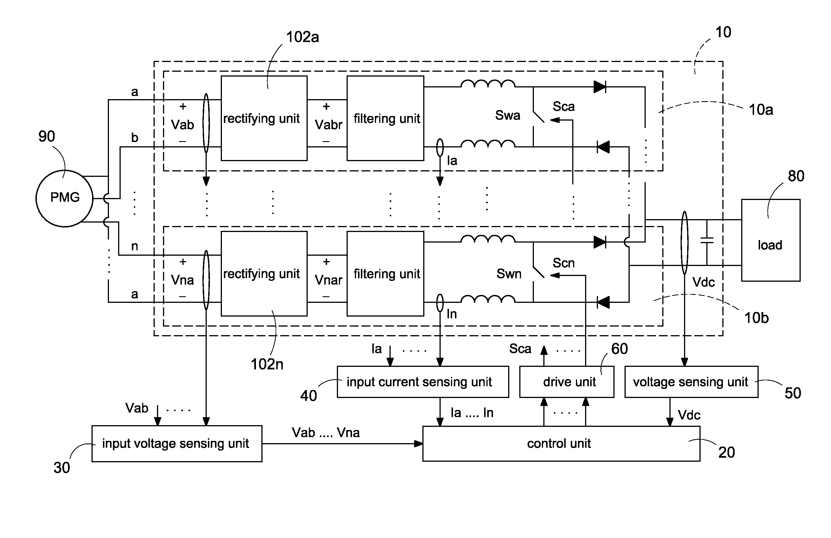
[0022]Reference is made to FIG. 3A which is a schematic circuit block diagram of a parallel-connected power conversion system of a multi-phase generator according to the present invention. The parallel-connected power conversion system provides a power factor correction to a multi-phase generator 90. In particular, the multi-phase generator 90 is a multi-phase permanent magnet generator (PMG). The multi-phase generator 90 is driven by an external force, such as wind power, hydraulic power, vapor power, or even human power. However, the embodiments are only exemplified but are not intended to limit the scope of the invention. For convenience, the wind power is exemplified to further demonstrate the present invention. In addition, the controller used in this present invention is a power conversion system which provide electromechanical energy coupling to the stator windings of the generator, and the controller can be installed inside the generator.

[0023]The parallel-connected power co...

second embodiment

[0031]Reference is made to FIG. 4B which is a schematic block diagram of the normalization operation unit of the control unit according to the present invention. The control unit 20 further includes a plurality of normalization operation units 2026a,2026b, . . . , 2026n. Each normalization operation unit 2026a,2026b, . . . , 2026n is connected to one of the multiplying units 2022a,2022b, . . . , 2022n, and correspondingly receives one of the rectified generator voltages Vabr,Vbcr, . . . , Vnar to correspondingly generate the voltage operation commands Va*,Vb*, . . . , Vn*. The normalization operation units 2026a,2026b, . . . , 2026n provide normalization operations to the received rectified generator voltages Vabr,Vbcr, . . . , Vnar. More specifically, each normalization operation unit 2026a,2026b, . . . , 2026n normalizes the correspondingly received rectified generator voltage Vabr,Vbcr, . . . , Vnar based on the maximum value of the rectified generator voltage Vabr,Vbcr, . . . , ...


PUM


Abstract

A parallel-connected power conversion system of a multi-phase generator configured to provide a power factor correction for a multi-phase generator. The parallel-connected power conversion system includes a parallel-connected power conversion apparatus and a control unit. The parallel-connected power conversion apparatus has a plurality of power conversion units connected in parallel to each other. The parallel-connected power conversion apparatus receives a plurality of generator currents and a plurality of generator voltages generated from the multi-phase generator, and outputs a DC voltage. The control unit generates a plurality of control signals to correspondingly control the power conversion units so that the generator currents linearly follow the generator voltages, therefore the power factor correction of the multi-phase generator is achieved.

Description

BACKGROUND[0001]1. Technical Field[0002]The present invention generally relates to a power conversion system of a multi-phase generator and a method of operating the same, and more particularly to a parallel-connected power conversion system of a multi-phase generator with a power factor correction function and a method of operating the same.[0003]2. Description of Related Art[0004]At present, the common converters of the power generation system can be roughly divided into two system structures: a passive rectification structure and an active rectification structure. Reference is made to FIG. 1, which is a schematic circuit diagram of a related art power generation system with a passive rectifying converter. The power generation system has a passive full-bridge rectifier 10A electrically coupled to a permanent magnet generator (PMG) 20A. The passive full-bridge rectifier 10A is provided to convert a three-phase AC voltage outputted from the permanent magnet generator 20A into a sing...

Claims


Application Information

Patent Timeline
Patent Type & Authority Applications(United States)
IPC IPC(8): H02M3/07
CPCH02M3/07H02M1/4225H02M7/23H02J2300/28H02J3/381Y02B70/10Y02E10/76Y02P80/10H02J3/38
Inventor HSIAO, CHIH-HUNGWEI, JO-FANGHSIAO, LI-WEI
Owner DELTA ELECTRONICS INC
Why Eureka
Try Eureka