Surgical instrument

a surgical instrument and op-aided technology, applied in the field of surgical instruments, can solve the problems of the sum of the different devices for the conventional op method and the computer-assisted surgery, the number of individual op steps, and the necessity of another device, so as to achieve the effect of quick connection to other attachments, rapid change into manual or computer-navigated surgery, and increased process safety

Inactive Publication Date: 2015-07-16
COMBROWSKI ZBIGNIEW
View PDF1 Cites 14 Cited by
  • Summary
  • Abstract
  • Description
  • Claims
  • Application Information

AI Technical Summary

Benefits of technology

[0024]Preferably, the shaft is suitable to attach an implant at its proximal end, particularly a screw with a cannula. Preferably, the shaft has a piece-by-piece cannula, preferably at one end. This offers the advantage that a guide-wire, a so-called K-Wire can be guided into the shaft.
[0078]A greater advantage is the suitable, simple manufacture which is especially very important in single use instruments. However, even in multi-piece instruments, these at least partially slotted configurations are easy, quicker to clean in finishing as well as after the operational defects and to sterilize and therefore are better reproducible and rather correspond to the present hygiene standards for achieving validated cleaning and sterilization processes in the field of medicine technology.

Problems solved by technology

Disadvantageously, another device is likewise necessary in order to determine the position of the screw.
Therefore, this is a very expensive Operation-Set, which includes many component parts.
The main problem of all the OP-Sets found in the market is the sum of the different devices for conventional OP methods and for the computer-assisted surgery as well as the number of the individual OP steps.
Consequently, the sets are large and are tuned for the individual OPs and need a lot of space for storage.
Thus, high costs of preparation and sterilization are involved.
Thus, the availability of such sets is also a big issue.
In all the mentioned devices, one disadvantage is common that a plethora of different instruments and devices and parts are required for an Operation Set.
These cannulae can be manufactured with much difficulty, because these instruments are usually very small and / or very long.
The materials are difficult to machine because of their hardness.
In addition, the drilling, gun drilling and grinding are very costly manufacturing processes.
A big disadvantage of these cannulated instruments during the operation is also, for example that the material reaches in the long cannula and jams the guide-wire and then rotates therewith.
Thus, the guide-wire is inserted deeper than desired, which may lead to complications during the operation.
Even cleaning of these cannulae after the operation is very difficult and complex.
Even here, the manufacture very costly, because initially these grooves have to be milled and then ground.
Furthermore, small drills are very delicate and can easily break off, especially due to the usual two flutes.

Method used


Image

  • Surgical instrument
  • Surgical instrument
  • Surgical instrument

Examples


Embodiment Construction

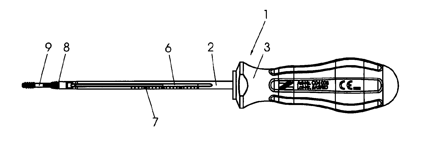
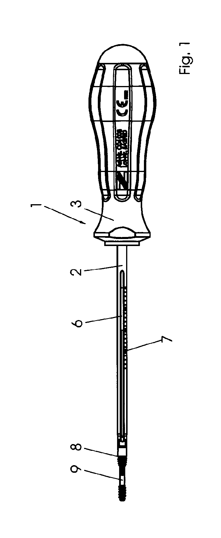
[0105]FIG. 1 shows a screwdriver with a cannulated shaft 2 and a grip 3, as a surgical instrument 1 in accordance with the invention.

[0106]The cannulated shaft 2 and the grip 3 can be either firmly connected or for example, interchangeably connected via a coupling.

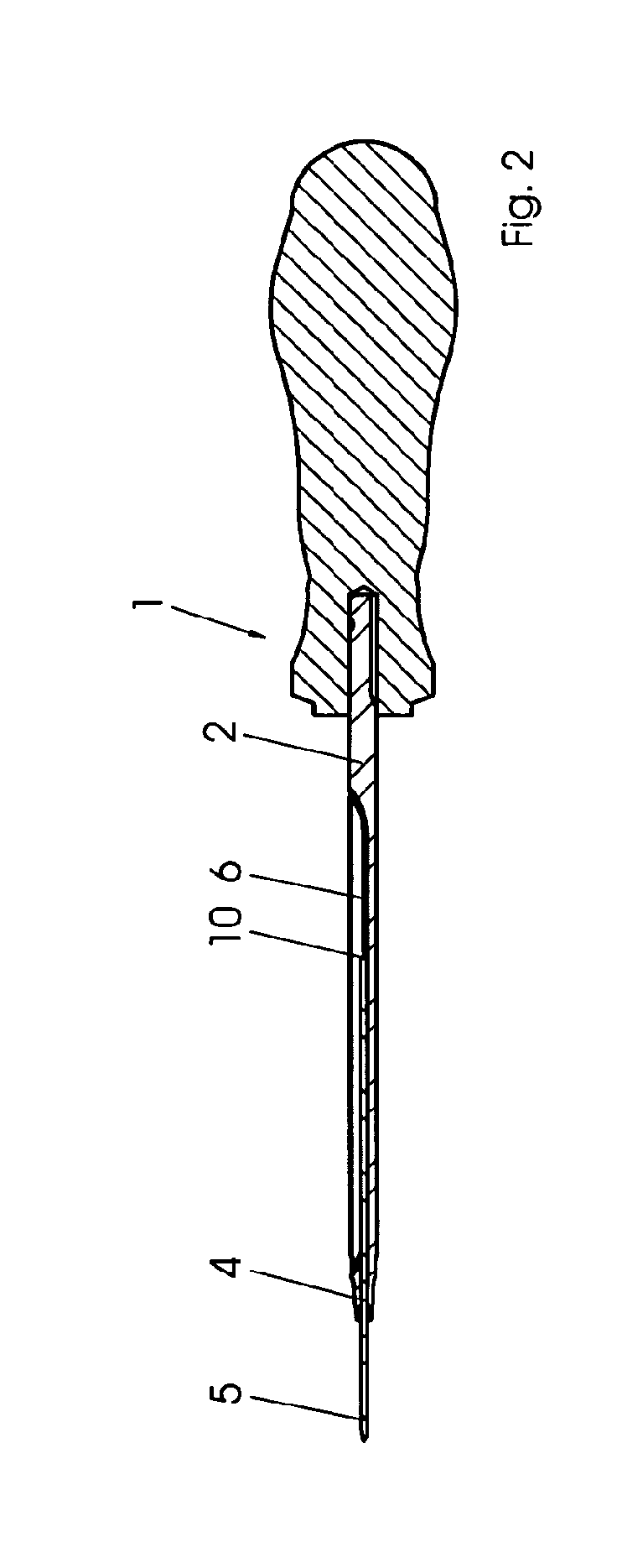
[0107]The cannulated shaft 2 is also represented in the FIGS. 2, 3, 4 and 5. As can be seen in the sectional representations of the FIGS. 2 and 5, the shaft 2 has a cannula 4. The cannula 4 is suitable for attaching a K-Wire 5 (so-called Kirschner Draht or Guide Wire) represented in the FIGS. 2 and 5. The cannulated shaft 2 has a slit 6, as represented in the FIGS. 1 to 5.

[0108]The slit 6 connects the cannula 4 with an outer surface of the shaft 2.

[0109]It should be noted for the manufacturing process the shaft 2 that in this option, initially a cannula is introduced and then the shaft is slit open up to the cannula. Furthermore, a method of manufacture can also be conceived, in which a thick shaft is slotted and subsequen...


PUM

PropertyMeasurementUnit
lengthaaaaaaaaaa
breakingaaaaaaaaaa
CTaaaaaaaaaa

Abstract

A surgical instrument (1, 12) for introducing an implant, comprising a shaft (2), wherein the shaft is suitable for accommodating the implant, in particular a screw (9, 15) having a cannula (4), at the proximal end of the shaft, wherein the shaft (2) has a cannulation, and a handle (3), which is connected to the shaft (2) at a distal end of the shaft (2). The shaft (2) is provided with a slit (6).

Description

BACKGROUND OF THE INVENTION[0001]The invention relates to a surgical instrument and, more particularly, a shaft for a surgical instrument.[0002]For connecting bone pieces, e.g. in Osteotomies or Traumas, different screw implants are also employed with Snap-Off-Shaft and in conjunction with bone plates.[0003]In order to obtain the desired properties of the bone joints, the screw-length and screw-position of the screw must be matched with the bone-pieces to be joined.[0004]Nowadays, it is done in non-cannulated screws, e.g. by measuring devices, such as bore-depth gauge or e.g. under CT or X-ray, wherein for safety, the screw-length or the bore-depth is always checked with a measuring device found in the OP-Set. Some manufacturers also offer in the set, instruments for manual navigation of the screw-position.[0005]According to the type of the screw, e.g. cannulated screws for determining the screw-length and for secured positioning of the screw, a guide-wire with a defined length is a...

Claims


Application Information

Patent Timeline
Patent Type & Authority Applications(United States)
IPC IPC(8): A61B17/88
CPCA61B17/8875A61B17/88A61B17/8886A61B2090/037A61B2090/061A61B2090/062
Inventor COMBROWSKI, ZBIGNIEW
Owner COMBROWSKI ZBIGNIEW
Why Eureka
Try Eureka