Impact body for hydraulic impact device

a technology of hydraulic hitting device and impact body, which is applied in the direction of manufacturing tools, percussive tools, portable drilling machines, etc., can solve the problems of increasing the loss of fluid in the duct, a lot of production cost and long production time, so as to reduce production costs and time, and reduce the effect of machining tim

Active Publication Date: 2015-07-16
LEE IL JAE
View PDF14 Cites 6 Cited by
  • Summary
  • Abstract
  • Description
  • Claims
  • Application Information

AI Technical Summary

Benefits of technology

[0020](1) The production costs and time can be reduced since only the cylinder liner inserted into the body requires to be machined precisely.
[0021](2) The production costs and time can be reduced since only the cylinder requires to be treated by heat.
[0022](3) It takes less time for machining since a high pressure port and a low pressure port communicate directly with a high pressure space groove and a low pressure space groove, the efficiency of the apparatus becomes good

Problems solved by technology

(1) Since the large body should be overall precisely machined so as to minimize the clearance between the outer periphery and the inner wall off the piston, it takes a lot of the production cost and a long production time.
(2) Since the piston is shocked and reciprocated inside the body, it is accompanied by intense pressure and heat. Accordingly, si

Method used


Image

  • Impact body for hydraulic impact device
  • Impact body for hydraulic impact device
  • Impact body for hydraulic impact device

Examples


Embodiment Construction

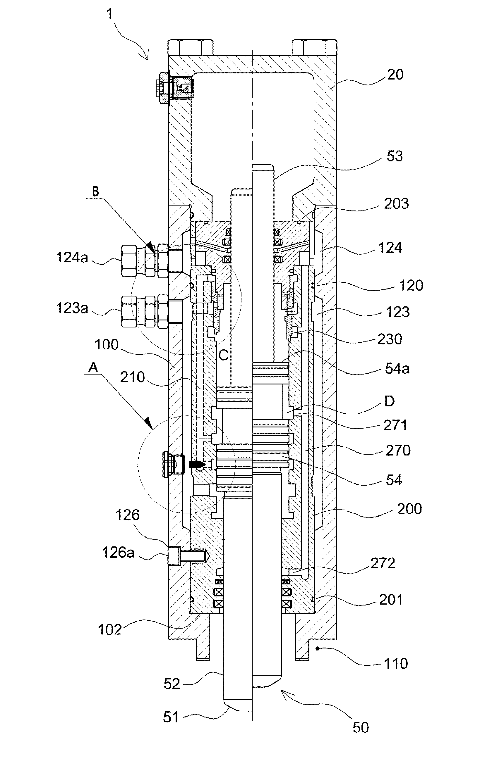
[0079]A hitting body 1 for a general hydraulic stroke device according to the present invention having a body 100, a piston 50 formed at the inside of the body 100, and an upper body 20 formed on the upper portion of the body 100 includes: a cylinder liner 200 inserted into and formed at the inside of the body 100; at least one operating flow path hole 210 and return flow path hole 270 formed at a wall of the cylinder liner 200 respectively; and a circular valve 230 formed between the seal retainers 240, which are formed at the upper end thereof.

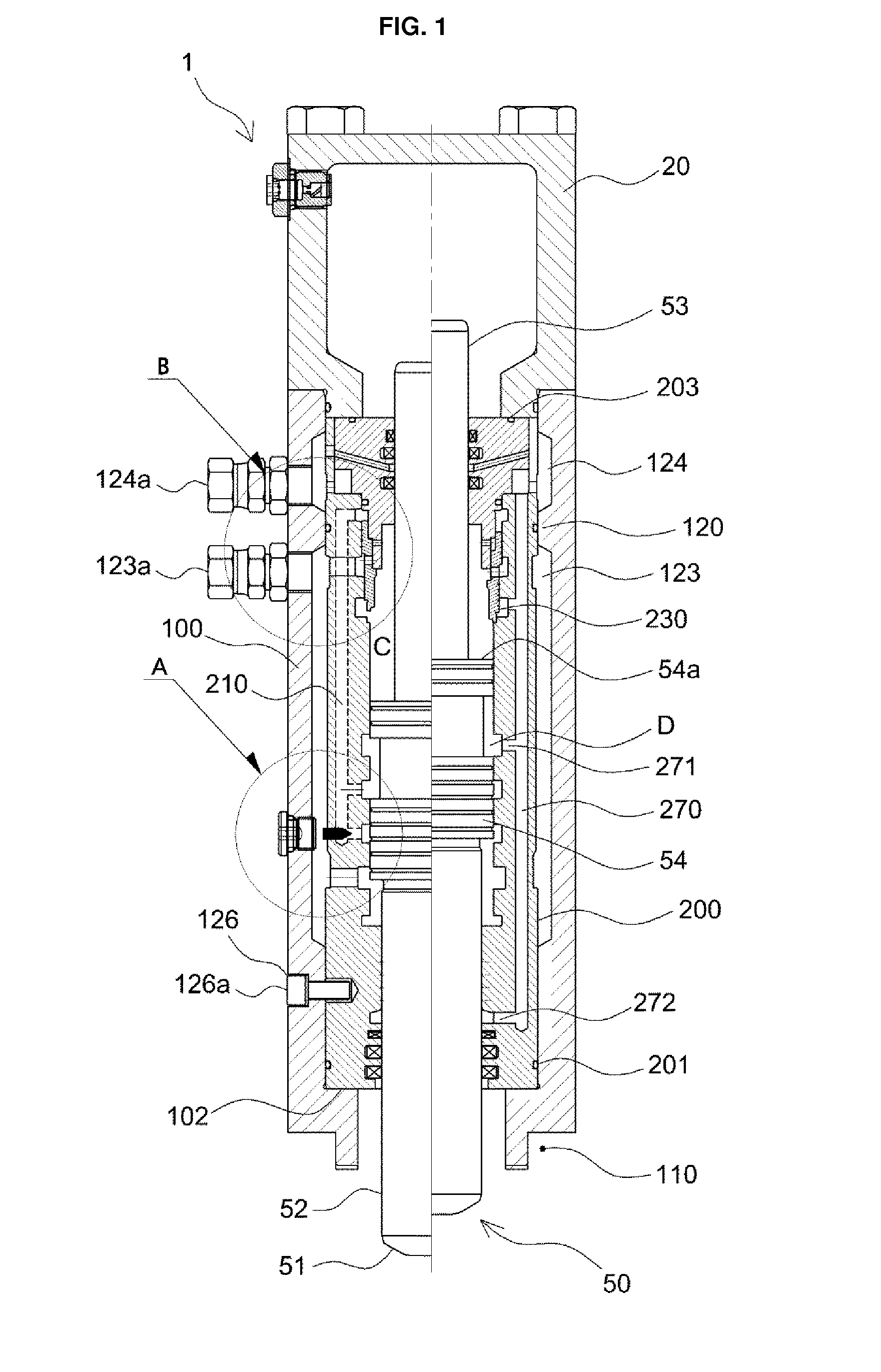
[0080]The body 100 includes a connection portion 110 formed at a lower portion thereof; a hole penetrated through the inside thereof; the liner fixing projection 102 formed on the lower portion of the hole; and a high pressure space groove 123 and a low pressure space groove 124 formed at the inner wall thereof and bounded by a separating projection 120.

[0081]The high pressure space groove 123 of a cylinder shape formed long along the inner ...


PUM

PropertyMeasurementUnit
Pressureaaaaaaaaaa
Impact strengthaaaaaaaaaa

Abstract

The present invention relates to a impact body for a hydraulic impact device and, more specifically, to a impact body for a hydraulic impact device which is capable of remarkably reducing production costs by inserting a cylinder liner having a flow path into an inner wall of a body, adjusting an impact interval and an impact strength according to the properties of a material to be crushed by adjusting an impact distance of a piston, minimizing the loss of a fluid in a pipe by forming a cylindrical flow path between the body and the cylinder liner, and remarkably improving performance by employing a circular valve to shorten the flow path whereby reduction of pressure is minimized.

Description

REFERENCE TO RELATED APPLICATIONS[0001]This application is a U.S. National Phase application of pending International Application No. PCT / KR2013 / 005484 filed on Jun. 21, 2013, and claims priority of Korean Patent Application No. 10-2012-0072428 filed on Jul. 3, 2012, the entire contents of which are incorporated herein by reference.FIELD OF THE INVENTION[0002]The present invention relates to a hitting body for a hydraulic hitting device and, more specifically, to a hitting body for a hydraulic hitting device which is capable of remarkably reducing production costs by inserting a cylinder liner having a flow path into an inner wall of a body, adjusting a hitting interval and a hitting strength according to properties of a material to be crushed by adjusting a hitting distance of a piston, minimizing the loss of fluid in a duct by forming a cylindrical flow path between the body and the cylinder liner, and minimizing reduction of pressure by employing a circular valve to shorten the f...

Claims


Application Information

Patent Timeline
IPC IPC(8): E21B4/14E02D7/10
CPCE02D7/10E21B4/14B25D17/00B25D9/12B25D9/18B25D2250/065B25D2250/105B25D2250/121B25D2250/231E21B1/36E02F3/966
Inventor LEE, IL JAE
Owner LEE IL JAE
Why Eureka
Try Eureka