

Turbine blade having swirling cooling channel and cooling method thereof
a turbine blade and cooling channel technology, applied in the field of turbine blades, can solve problems such as damage to the root unit b>1/b>, and achieve the effect of improving the stiffness of the root unit and increasing the cooling performance of the root uni
- Summary
- Abstract
- Description
- Claims
- Application Information
AI Technical Summary
Benefits of technology
Problems solved by technology
Method used
Image

Examples
first embodiment
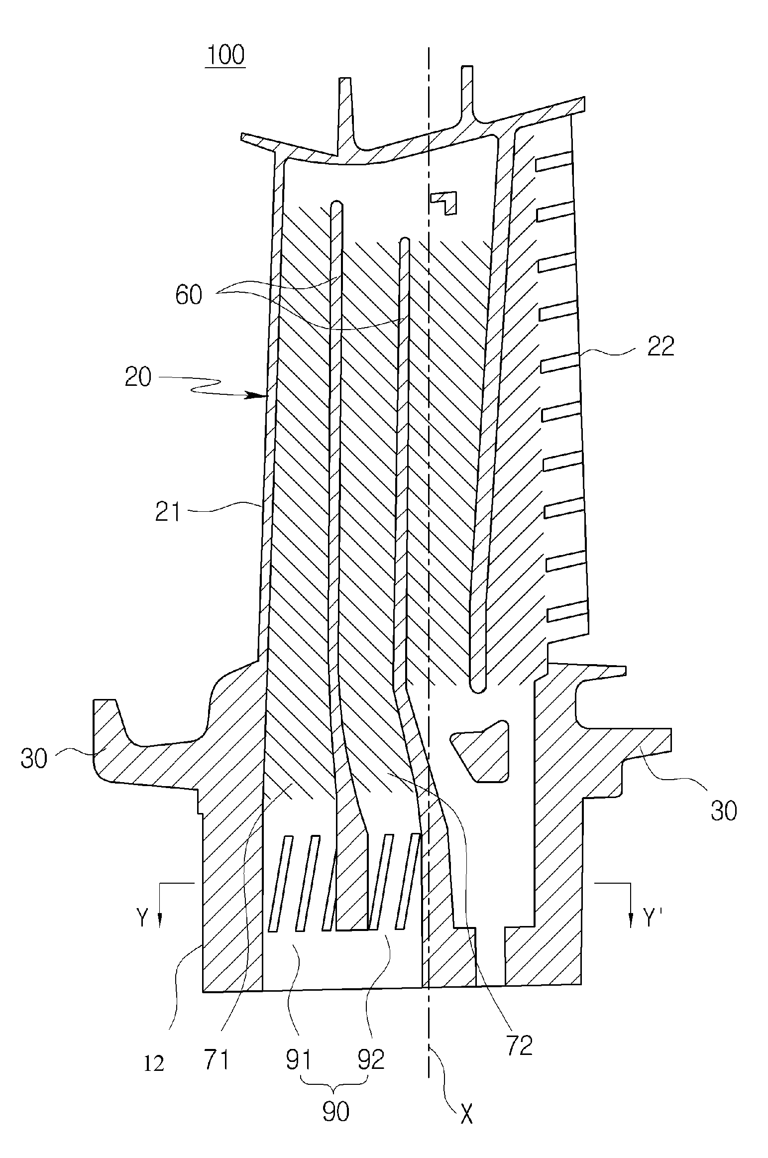
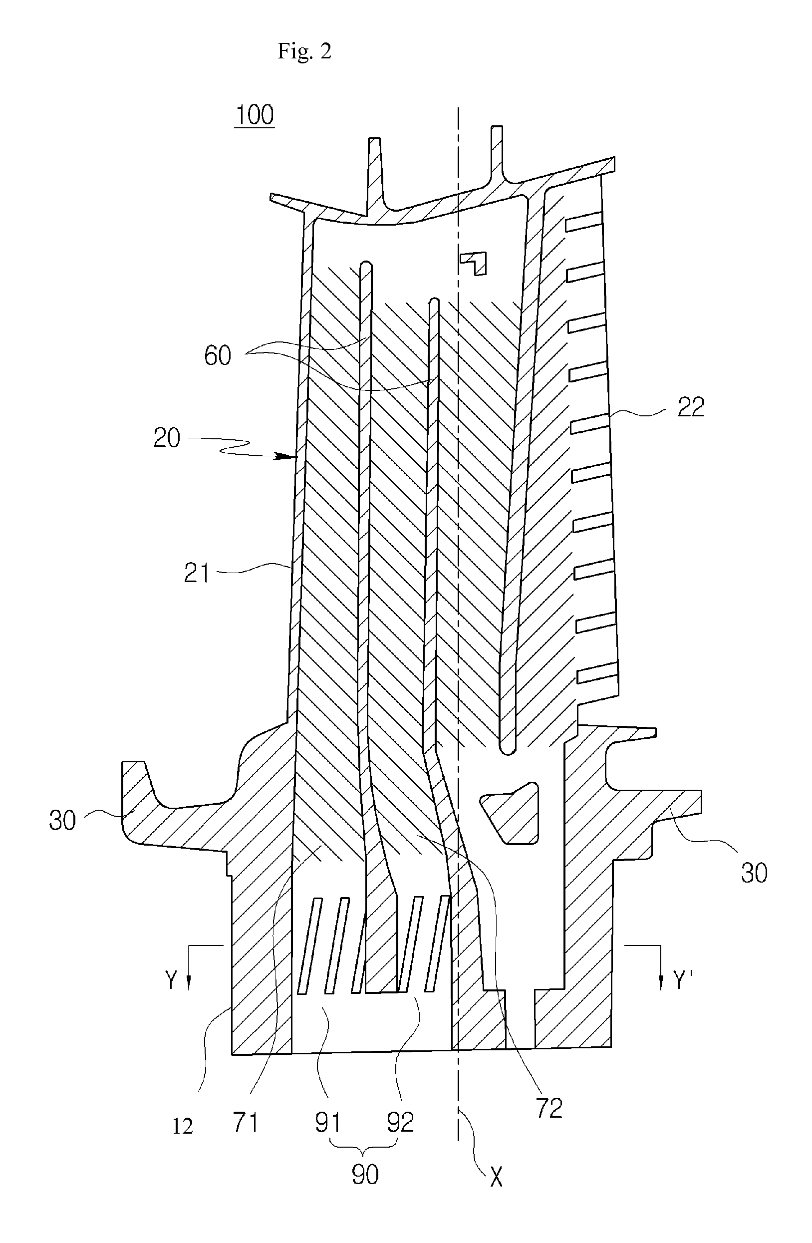
[0046]FIG. 2 is a longitudinal cross-sectional view of a turbine blade 100 with a swirl portion 80 (see also FIG. 3) according to the present disclosure. FIG. 3 is a partially expanded view of the turbine blade 100 illustrated in FIG. 2.
[0047]Referring to FIGS. 2 and 3, the turbine blade 100 according to the embodiment of the present disclosure includes a root unit 12, a blade unit 20 having a leading edge 21 and a trailing edge 22, and a platform unit 30 provided between the blade unit 20 and the root unit 12. The blade unit 20 has a cooling channel 70 formed therein, through which cooling air is passed. The cooling channel 70 includes a first cooling channel 71 formed adjacent to the leading edge 21 and extended in the longitudinal direction of the blade unit 20 and a second cooling channel 72 formed between the first cooling channel 71 and the trailing edge 72 and extended in the longitudinal direction. The root unit 12 or the platform unit 30 includes first and second entrances ...
third embodiment
[0057]FIG. 5 is a partially expanded view of a turbine blade 100 with a swirl portion 80 according to the present disclosure.
[0058]Referring to FIG. 5, the swirl portion 80 according to the third embodiment of the present disclosure includes a first swirl portion 81 provided at a first entrance 91 and a second swirl portion 82 provided at a second entrance 92. The first swirl portion 82 includes a plurality of first guide ribs 83 which are formed to protrude from the inner circumferential surface of the first entrance 91 and extend in the upward direction or the longitudinal direction of the blade unit 20 while forming a first inclination angle a1 with respect to the longitudinal direction. The second swirl portion 83 includes a plurality of second guide ribs 84 which are formed to protrude from the inner circumferential surface of the second entrance 92 and extend in the upward direction or the longitudinal direction of the blade unit 20 while forming a second inclination angle a2 ...
fourth embodiment
[0063]Referring to FIG. 6, the swirl portion 80 according to the present disclosure may include a first swirl portion 81 provided at a first entrance and a second swirl portion 82 provided at a second entrance, and the number of first guide ribs 83 formed in the first swirl portion 81 may be set to be different from the number of second guide ribs 84 formed in the second swirl portion 82. Desirably, the number of first guide ribs 83 may be set to be larger than the number of second guide ribs 84.
[0064]As the number of first guide ribs 83 formed in the first swirl portion 81 may be set to be different from the number of second guide ribs 84 formed in the second swirl portion 82, it is possible to adjust the strength of a swirl flow generated through the first swirl portion 81 and the strength of a swirl flow generated through the second swirl portion 82. Desirably, in order to achieve a higher heat transfer effect, the number of first guide ribs 83 may be set to be larger than the nu...
PUM
 Abstract
Description
Claims
Application Information