Vibration-reducing structure for compressing diaphragm pump

a diaphragm pump and vibration-reducing technology, which is applied in the direction of pump control, pump components, positive displacement liquid engines, etc., can solve the problems of long-standing serious drawbacks of forgoing other parts of conventional compressing diaphragm pumps also shaking simultaneously, and the whole conventional compressing diaphragm pump vibrates directly, etc., to achieve shorten the length of the moment arm, reduce the torque, and reduce the torqu

Inactive Publication Date: 2015-07-16
CAI YING LIN +1
View PDF4 Cites 12 Cited by
  • Summary
  • Abstract
  • Description
  • Claims
  • Application Information

AI Technical Summary

Benefits of technology

[0012]An objective is to provide a vibration-reducing method for a compressing diaphragm pump that features of a vibration-reducing unit. The compressing diaphragm pump includes a brushed or brushless motor with an output shaft, a pump head cover, a motor upper chassis, a wobble plate with integral protruding cam-lobed shaft, an eccentric roundel mount with three eccentric roundels, a pump head body, a diaphragm membrane with three piston acting zones, three pumping pistons and a piston valvular assembly. The vibration-reducing unit is disposed between the pump head body and diaphragm membrane. The vibration-reducing unit functions for diminishing torque by shortening the length of the moment arm for the circumnutating action of the eccentric roundel mount in each piston acting zone. Since the torque is the equal to the length of moment arm multiplied by a constant acting force, a lower torque is generated by the shortened length of moment arm. Consequently, with less torque for the compressing diaphragm pump, the strength of vibration is substantially reduced, with a consequent lowering of annoying vibration noise.
[0013]Another objective is to provide a vibration-reducing method for a compressing diaphragm pump that features a vibration-reducing unit disposed between a pump head body with three basic curved indents and a diaphragm membrane with three basic curved protrusions, in which the three basic curved protrusions are completely inserted into the corresponding three basic curved indents. The vibration-reducing unit functions to diminish torque by shortening the length of the moment arm for each piston acting zone upon circumnutating action of the eccentric roundel mount. Because the torque is obtained by multiplying the length of the moment arm by a constant acting force, is reduced due to the shortened length of moment arm, the strength of vibration and the resulting vibration noise is also substantially reduced.

Problems solved by technology

Referring to FIGS. 12 through 14, a primary serious drawback has long existed in the foregoing conventional compressing diaphragm pump.
However, the resultant torque causes the whole conventional compressing diaphragm pump to vibrate directly.
This synchronous shaking” of the water pipe P will further cause other parts of the conventional compressing diaphragm pump to also simultaneously shake.
Consequently, the overall resonant shaking aforesaid will cause vibration of the housing C of the reverse osmosis purification unit to become stronger, increasing vibration noise and, after a certain period, causing water leakage of the conventional compressing diaphragm pump due to a gradually loosened connection between water pipe P and water outlet orifice 22, as well as gradual loosening of other parts affected by the shaking.
However, the practical vibration suppressing efficiency of using foregoing cushion base 100 with wing plates 101 and rubber shock absorber 102 only affects the primary vibrating drawback to a limited degree, and does not solve the drawbacks of overall resonant shaking or water leakage for the conventional compressing diaphragm pump.
The problem of substantially reducing all of the drawbacks associated with the operating vibration of the compressing diaphragm pump has become an urgent and critical issue.

Method used


Image

  • Vibration-reducing structure for compressing diaphragm pump
  • Vibration-reducing structure for compressing diaphragm pump
  • Vibration-reducing structure for compressing diaphragm pump

Examples


Embodiment Construction

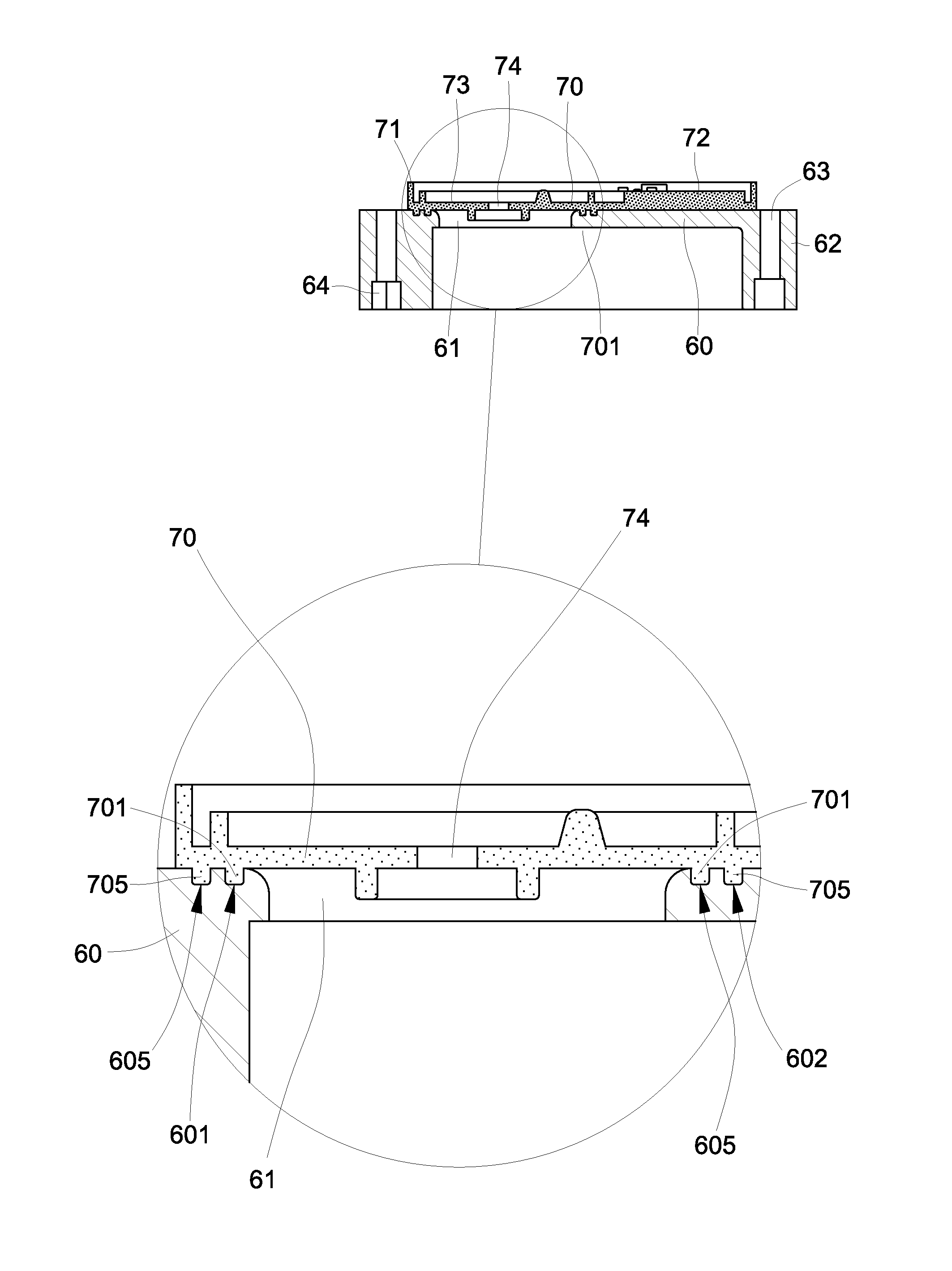
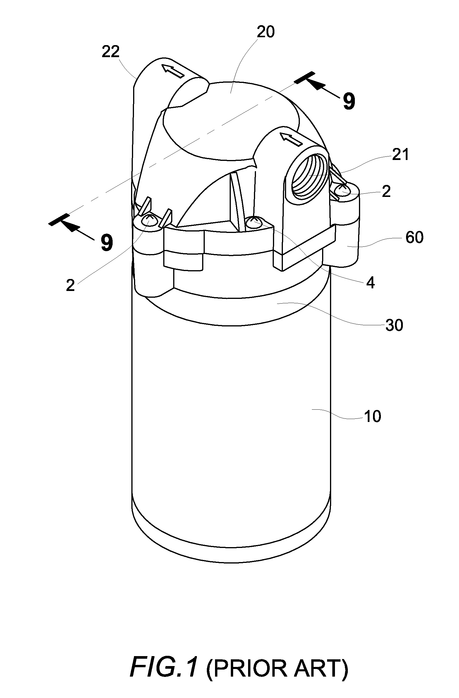
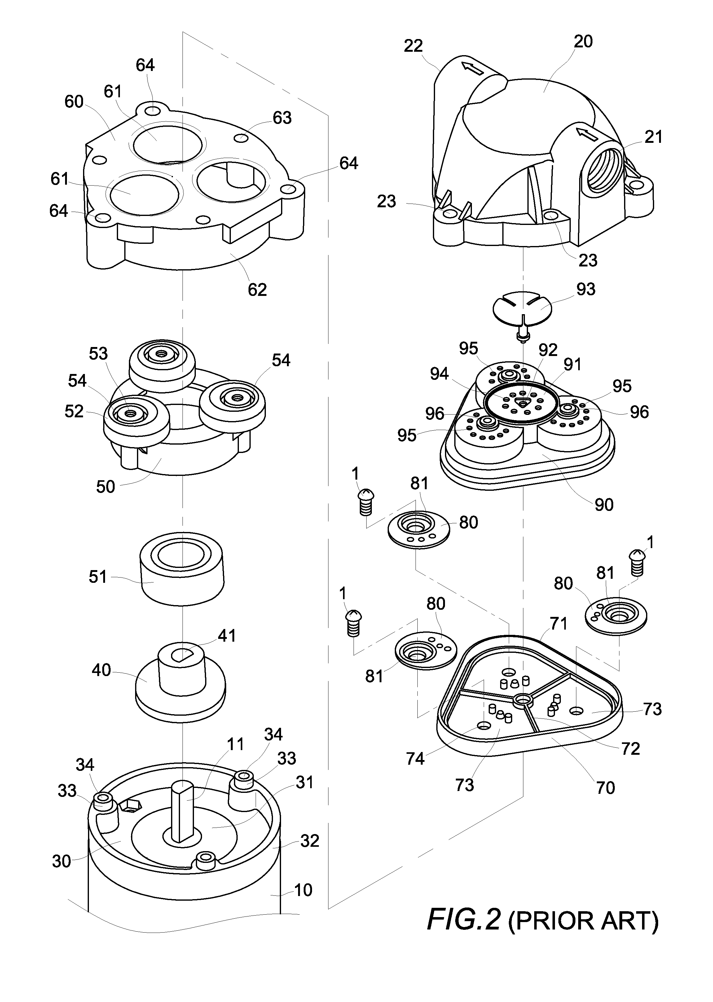
[0074]FIGS. 15 through 59 are illustrative figures for the vibration-reducing method for compressing diaphragm pump of the present invention. The compressing diaphragm pump comprises a motor 10 with an output shaft 11, a pump head cover 20, a motor upper chassis 30, a wobble plate 40 with integral protruding cam-lobed shaft, an eccentric roundel mount 50, a pump head body 60, a diaphragm membrane 70, three pumping pistons 80 and a piston valvular assembly 90, wherein, except as described below, components included in each part may be the same as those in the conventional compressing diaphragm pump as described above.

[0075]The basic operation mode of the compressing diaphragm pump is as follows: When the motor 10 is powered on, the wobble plate 40 is driven to rotate by the motor output shaft 11 so that three eccentric roundels 52 on the eccentric roundel mount 50 sequentially and constantly move in up-and-down reciprocal stroke. Meanwhile, three pumping pistons 80 and three piston a...


PUM


Abstract

A vibration-reducing method for reducing vibrations and vibration noise in a compressing diaphragm pump includes the step of disposing a vibration-reducing unit between the pump head body and a diaphragm membrane to reduce a length of the moment arm, and therefore of the torque, generated upon up and down movement of the diaphragm membrane during pumping.

Description

[0001]This application claims the benefit of provisional U.S. Patent Application No. 61 / 928,162, filed Jan. 16, 2014, and incorporated herein by reference.FIELD OF THE PRESENT INVENTION[0002]The present invention relates to a vibration-reducing method for compressing diaphragm pump used in a reverse osmosis purification system, and particularly to a method that utilizes a vibration-reducing unit to reduce the vibration strength of the pump so that the annoying noise incurred by consonance with the housing of the reverse osmosis purification system is eliminated when the vibration-reducing unit is installed thereon.BACKGROUND OF THE INVENTION[0003]Conventional compressing diaphragm pumps, which have been exclusively used with RO (Reverse Osmosis) purifier or RO water purification systems, are disclosed in U.S. Pat. Nos. 4,396,357, 4,610,605, 5,476,367, 5,571,000, 5,615,597, 5,626,464, 5,649,812, 5,706,715, 5,791,882, 5,816,133, 6,048,183, 6,089,838, 6,299,414, 6,604,909, 6,840,745 an...

Claims


Application Information

Patent Timeline
Patent Type & Authority Applications(United States)
IPC IPC(8): F04B45/047
CPCF04B45/047F04B39/0044F04B43/026F04B53/003
Inventor CAI, YING LINHSU, CHAO FOU
Owner CAI YING LIN
Why Eureka
Try Eureka