Lead-acid battery
a lead-acid battery and storage battery technology, applied in the direction of batteries, sustainable manufacturing/processing, cell components, etc., can solve the problems of lead-acid battery life likely to decrease, insufficient charge state, etc., and achieve the effect of sufficient charge acceptance, sufficient durability, and sufficient charge recovery
- Summary
- Abstract
- Description
- Claims
- Application Information
AI Technical Summary
Benefits of technology
Problems solved by technology
Method used
Image
Examples
first embodiment
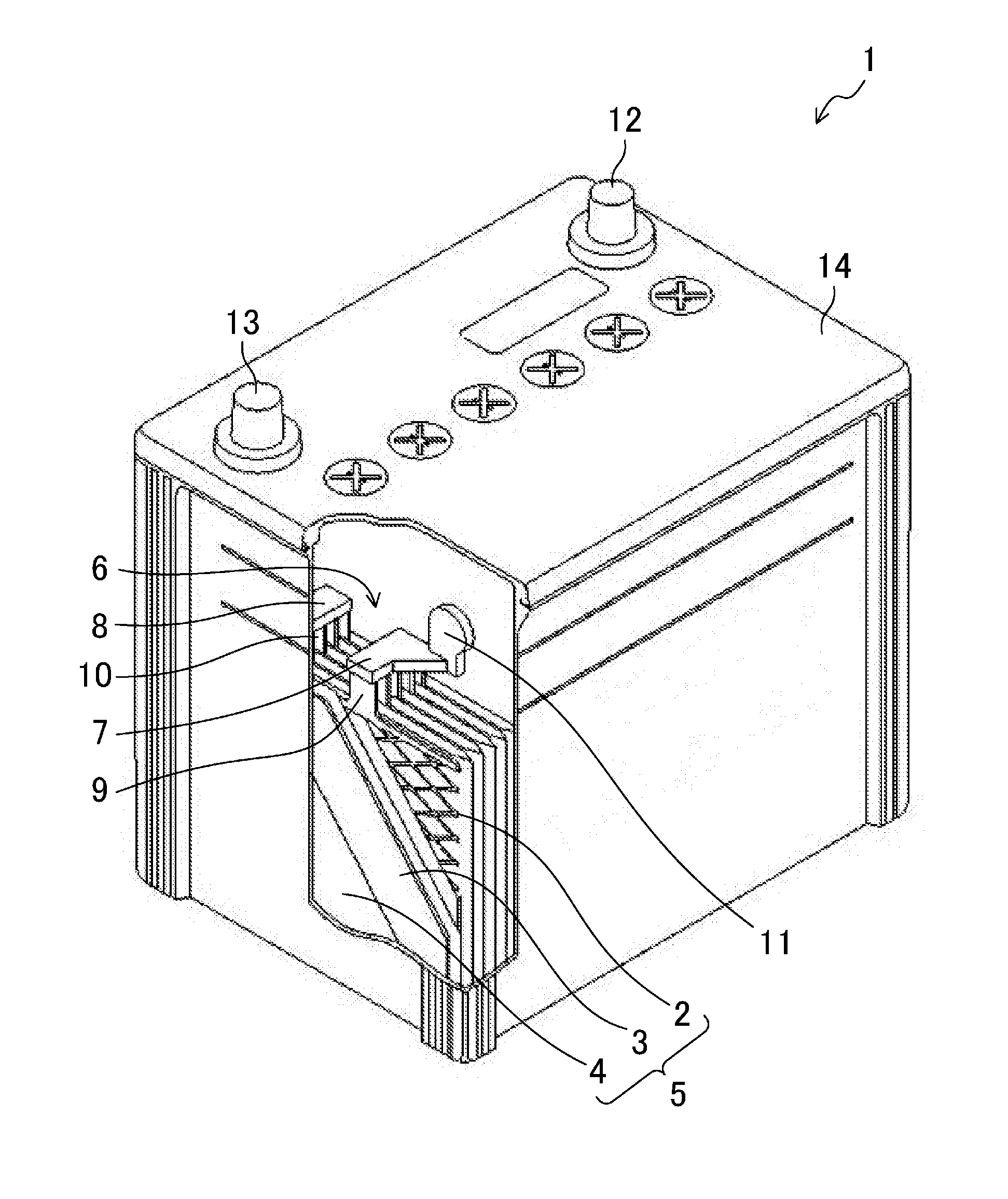
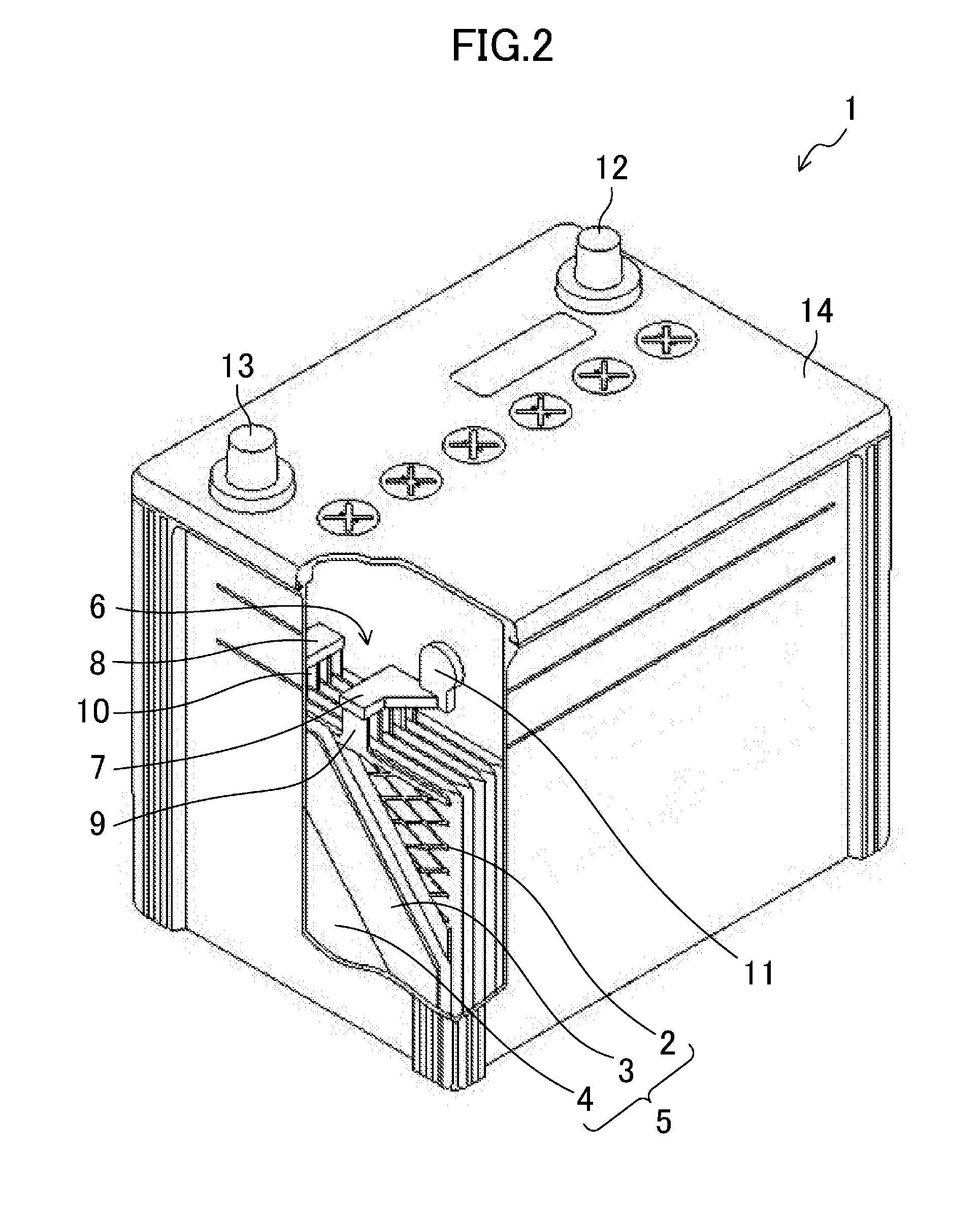
[0034]FIG. 2 is a schematic view illustrating an outline configuration of a lead-acid battery 1 of a first embodiment of the present invention.
[0035]Referring to FIG. 2, in the lead-acid battery 1, an electrode plate group 5 in which a plurality of positive electrode plates 2 and a plurality of negative electrode plates 3 are stacked on each other with a separator 4 being interposed between adjacent ones of the positive and negative electrode plates 2, 3 is housed in each cell chamber 6 together with an electrolyte.
[0036]The positive electrode plate 2 includes a positive electrode grid and a positive electrode active material with which the positive electrode grid is filled, and the negative electrode plate 3 includes a negative electrode grid and a negative electrode active material with which the negative electrode grid is filled. Note that the positive and negative electrode grids of the present embodiment are made of lead or a lead alloy containing no antimony (Sb), such as a Pb...
first example
[0044]The configuration and advantages of the present invention will be further described below with reference to examples of the present embodiment. Note that the present invention is not Limited to these Examples.[0045](1) Formation of Lead-Acid Battery
[0046]Lead-acid batteries 1 formed in the present examples are liquid lead-acid batteries having a D23L size specified in JIS D 5301. Seven positive electrode plates 2 and eight negative electrode plates 3 are housed in each cell chamber 6, and each negative electrode plate 3 is housed in a bag-shaped separator 4 made of polyethylene.
[0047]Each positive electrode plate 2 was formed in such a manner that lead oxide powder is mixed with sulfuric acid and purified water to prepare a paste and an expanded grid made of a material having the composition of a calcium-based lead alloy is filled with the paste.
[0048]Each negative electrode plate 3 was formed in such a manner that an organic additive etc. are added to lead oxide powder, the r...
example 1-1
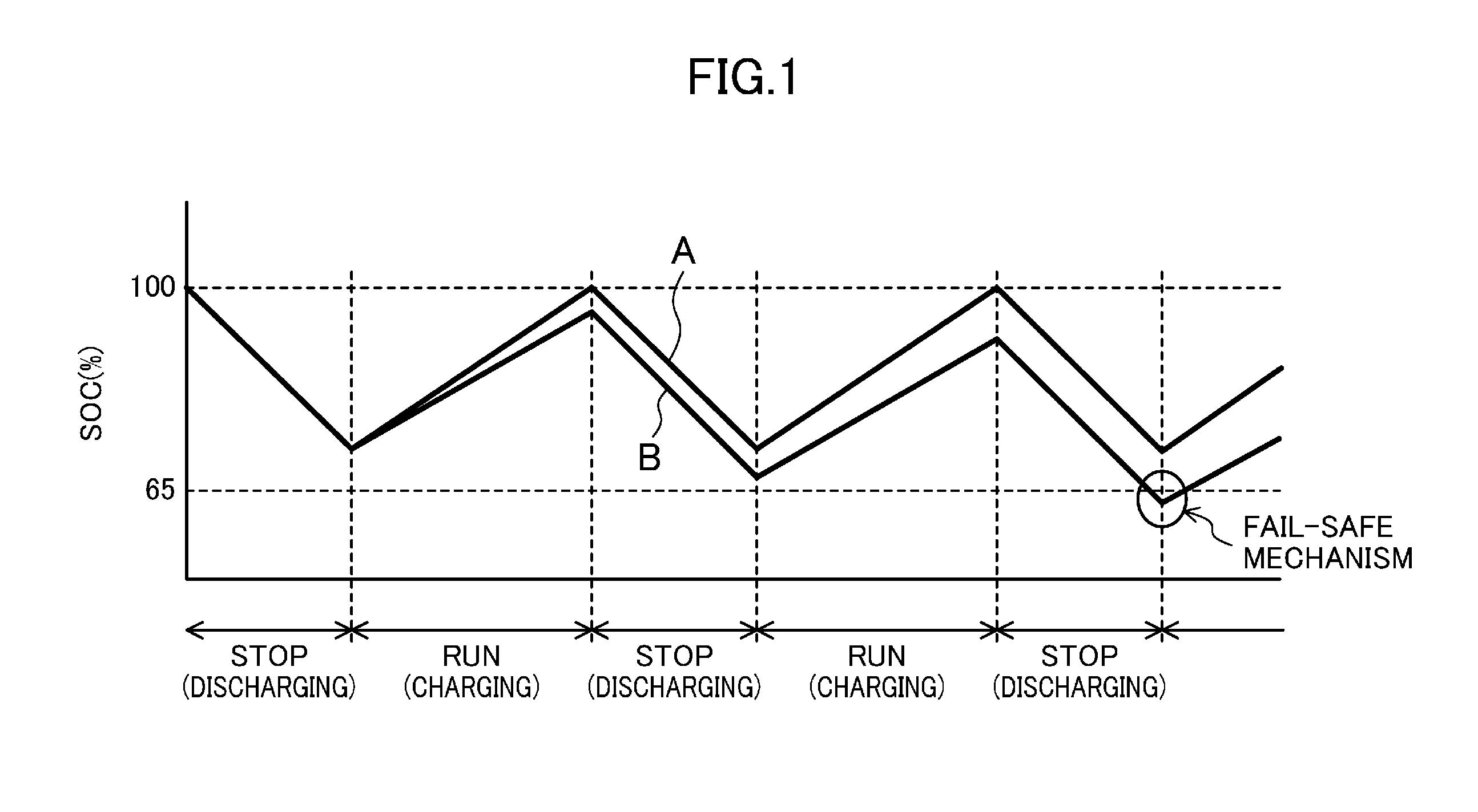
[0067]Batteries A1 to A7 were formed, in each of which a surface layer made of a lead alloy containing antimony is formed on a surface of a negative electrode grid and a mass ratio MN / MP falls within a range of 0.65 to 1.15, where “MP” represents the mass of a positive electrode active material per cell chamber and “MN” represents the mass of a negative electrode active material per cell chamber. The life characteristic of each battery and the characteristic of each battery in the short-distance drive mode were evaluated.
[0068]The negative electrode grid is formed of an expanded grid of Pb-1.2Sn-0.1Ca, and the surface layer is made of Pb-3mass % Sb foil. Moreover, a positive electrode grid is formed of an expanded grid of Pb-1.6Sn-0.1Ca, and no surface layer is formed on the positive electrode grid.
[0069]Table 1 shows the evaluation results of each characteristic. Note that a battery A8 in which no surface layer is formed on a surface of a negative electrode grid was formed as a com...
PUM
 Abstract
Description
Claims
Application Information
 - R&D
- Intellectual Property
- Life Sciences
- Materials
- Tech Scout
- Unparalleled Data Quality
- Higher Quality Content
- 60% Fewer Hallucinations
Browse by: Latest US Patents, China's latest patents, Technical Efficacy Thesaurus, Application Domain, Technology Topic, Popular Technical Reports.
© 2025 PatSnap. All rights reserved.Legal|Privacy policy|Modern Slavery Act Transparency Statement|Sitemap|About US| Contact US: help@patsnap.com


