
Digital holography device and digital holography play method

Inactive Publication Date: 2015-07-23
NAT UNIV KYOTO INST OF TECH
View PDF6 Cites 10 Cited by
  • Summary
  • Abstract
  • Description
  • Claims
  • Application Information

AI Technical Summary

Benefits of technology

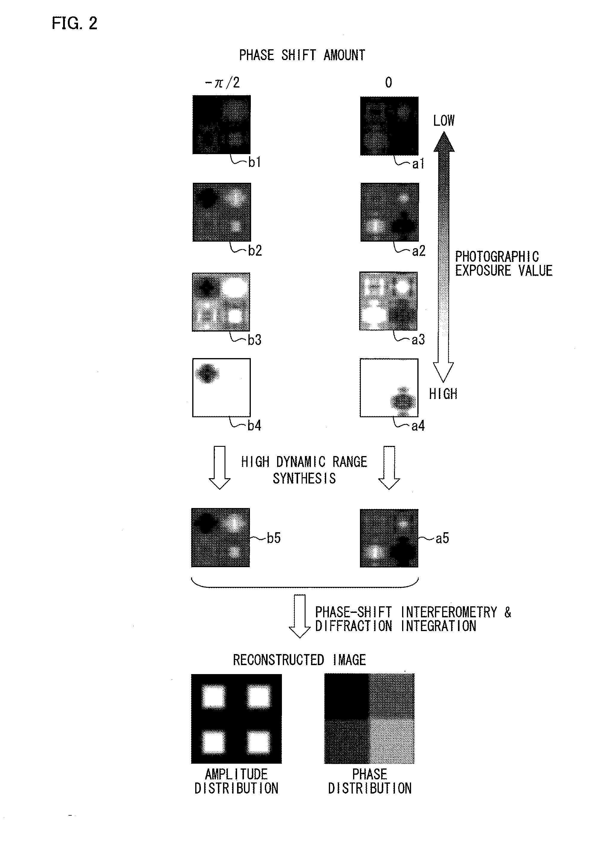
The present invention minimizes the impact of halation and blackening on a reconstructed image by creating a hologram with a high dynamic range. This allows for a sharp image to be reconstructed from a hologram that is not completely free of halation and blackening. The technical effect is an improved quality of the reconstructed image.

Problems solved by technology

In-line type digital holography has a problem that a reconstructed image is deteriorated because an unnecessary image component such as zeroth-order diffracted light or a conjugate image is included in data recorded by use of a CCD or the like.
However, employing the technology disclosed in Non-patent Literature 1 and Patent Literature 1 or off-axis type digital holography still has a problem.
That is, since recording of an interference pattern is performed by use of an image sensor, an interference pattern that contains a halation or a blackening is recorded due to an insufficient dynamic range of the image sensor.
This prevents a reconstructed image having a high image quality from being obtained.

Method used


Image

  • Digital holography device and digital holography play method
  • Digital holography device and digital holography play method
  • Digital holography device and digital holography play method

Examples


first embodiment

Phase-Shift DH Device

[0059]A First Embodiment will describe an example in which the present invention is applied to a phase-shift DH device.

[0060](Phase-Shift DH Device of Sequential Recording Type)

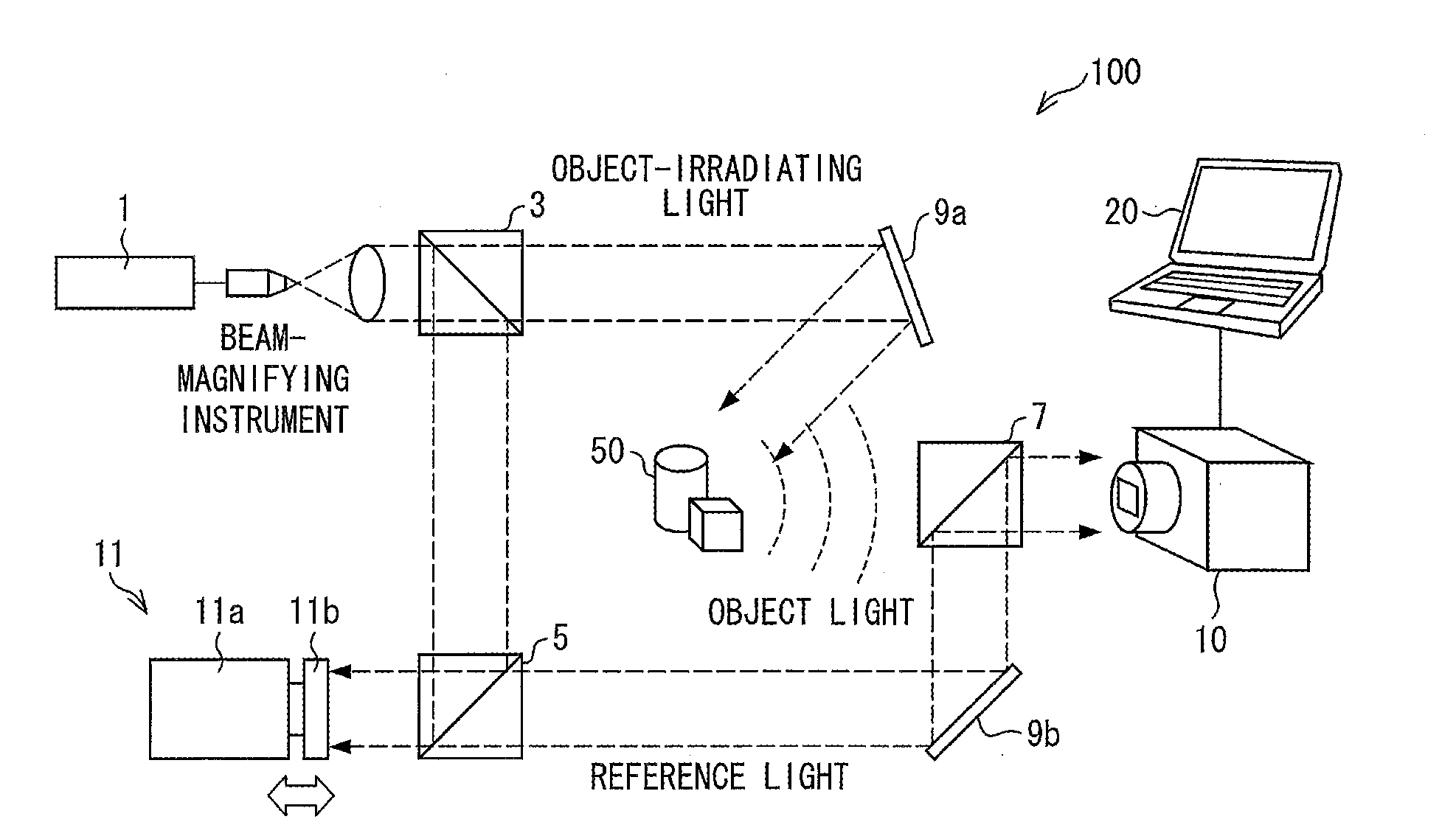
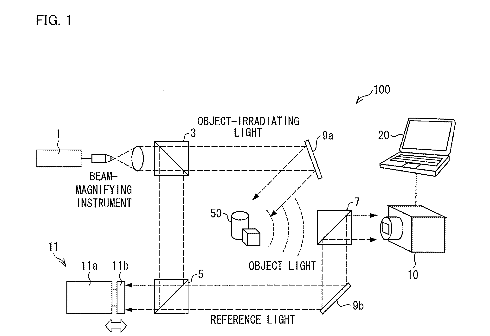
[0061]FIG. 1 is a view illustrating an example of a digital holography device in the First Embodiment of the present invention. As illustrated in FIG. 1, a phase-shift digital holography device 100, which is an example of the digital holography device, includes a laser 1, beam splitter elements 3 and 5, a beam-combining element 7, mirrors 9a and 9b, an image sensing device (recording section) 10, a piezoelectric element-driven reflecting mirror 11, and a computer 20.

[0062]The laser 1 emits vertically-polarized laser light, which then enters the beam splitter element 3 through a beam-magnifying instrument. The beam splitter element 3 is an optical element for splitting laser light, and causes laser light emitted from the laser 1 and having entered the beam splitter element 3 to be split in...

modified example 1

Phase-Shift DH Device of Simultaneous Recording Type

[0079]The phase-shift digital holography device 100 in the First Embodiment sequentially records holograms to thereby record a plurality of first hologram data elements corresponding to respective different photographic exposure values. A phase-shift digital holography device in a Modified Example 1 uses means for causing a photographic exposure value to vary from pixel to pixel, so that the phase-shift digital holography device records, simultaneously in a single-shot recording, a first parallel hologram obtained with use of a photographic exposure value that varies from pixel to pixel.

[0080]FIG. 6 illustrates an image sensing device in the Modified Example 1. As illustrated in FIG. 6, an image sensing device 10A includes a polarizer-array device (phase-shift array) 51 attached to an image sensor plane of the image sensing device 10A. Note that for easy explanation, FIG. 6 shows a structure of a partial region of the polarizer-arr...

modified example 2

Another Phase-Shift DH Device of Simultaneous Recording Type

[0099]A phase-shift digital holography device in a Modified Example 2 uses means for causing a photographic exposure value to vary from pixel to pixel, so that the phase-shift digital holography device records, simultaneously in a single-shot recording, a hologram obtained with use of a photographic exposure value that varies from pixel to pixel. The means is, however, different from the means in the Modified Example 1. Note that the phase-shift digital holography device in the Modified Example 2 differs the phase-shift digital holography device 100, described with reference to FIG. 1, in the First Embodiment in that the image sensing device 10 is replaced with an image sensing device 10B (see FIG. 9). Configurations and functions of the phase-shift digital holography device in the Modified Example 2 other than the image sensing device 10B are the same with those of the phase-shift digital holography device 100, and the fol...


PUM


Abstract

A digital holography device of an embodiment of the present invention includes: an image sensing device which records, in an image sensor and on the basis of an object, a plurality of holograms that correspond to respective different photographic exposure values; and a computer which (i) generates a high dynamic range hologram, which includes pieces of information ranging from low luminance information to high luminance information, by synthesizing the plurality of holograms recorded and (ii) generates a reconstructed image of the object by performing arithmetic processing of phase-shift interferometry, diffraction calculation, and / or the like on the basis of the high dynamic range hologram.

Description

TECHNICAL FIELD[0001]The present invention relates to a digital holography device and a digital holography reconstruction method.BACKGROUND ART[0002]Digital holography (hereinafter also referred to as ‘DH’) which utilizes interference of light is known as conventional art. Digital holography is technology in which an image of a three-dimensional object is reconstructed by use of a computer on the basis of an interference pattern obtained by irradiating the three-dimensional object with light. The interference pattern is formed by interference between (i) object light obtained by irradiating the three-dimensional object with light and (ii) reference light provided from a light source that is used for irradiating the three-dimensional object with light, and the interference pattern is recorded by use of an image sensor such as a CCD or a CMOS. On the basis of the interference pattern recorded, the computer performs diffraction calculation such as the Fresnel transformation, so that a ...

Claims


Application Information

Patent Timeline
IPC IPC(8): G03H1/08G03H1/10G03H1/18G03H1/04
CPCG03H1/0866G03H1/0443G03H2001/0883G03H1/182G03H1/10G03H2001/0447G03H2001/0458G03H2001/2655G03H2222/31G03H2223/19G03H2223/22G03H2240/52
Inventor AWATSUJI, YASUHIROYONESAKA, RYOSUKETAHARA, TATSUKI
Owner NAT UNIV KYOTO INST OF TECH
Learn More