Display device
- Summary
- Abstract
- Description
- Claims
- Application Information
AI Technical Summary
Benefits of technology
Problems solved by technology
Method used
Image

Examples
first embodiment
[0071]First, an example in which a display device provided with a touch panel as an input device is applied to an in-cell liquid crystal display device with a touch detection function will be described as the first embodiment. Note that an in-cell liquid crystal display device with a touch detection function indicates a liquid crystal display device with a touch detection function in which at least one of the driving electrodes and the detecting electrodes included in the touch panel are incorporated in the liquid crystal display device as the driving electrodes for driving liquid crystal of the liquid crystal display device.
[0072]
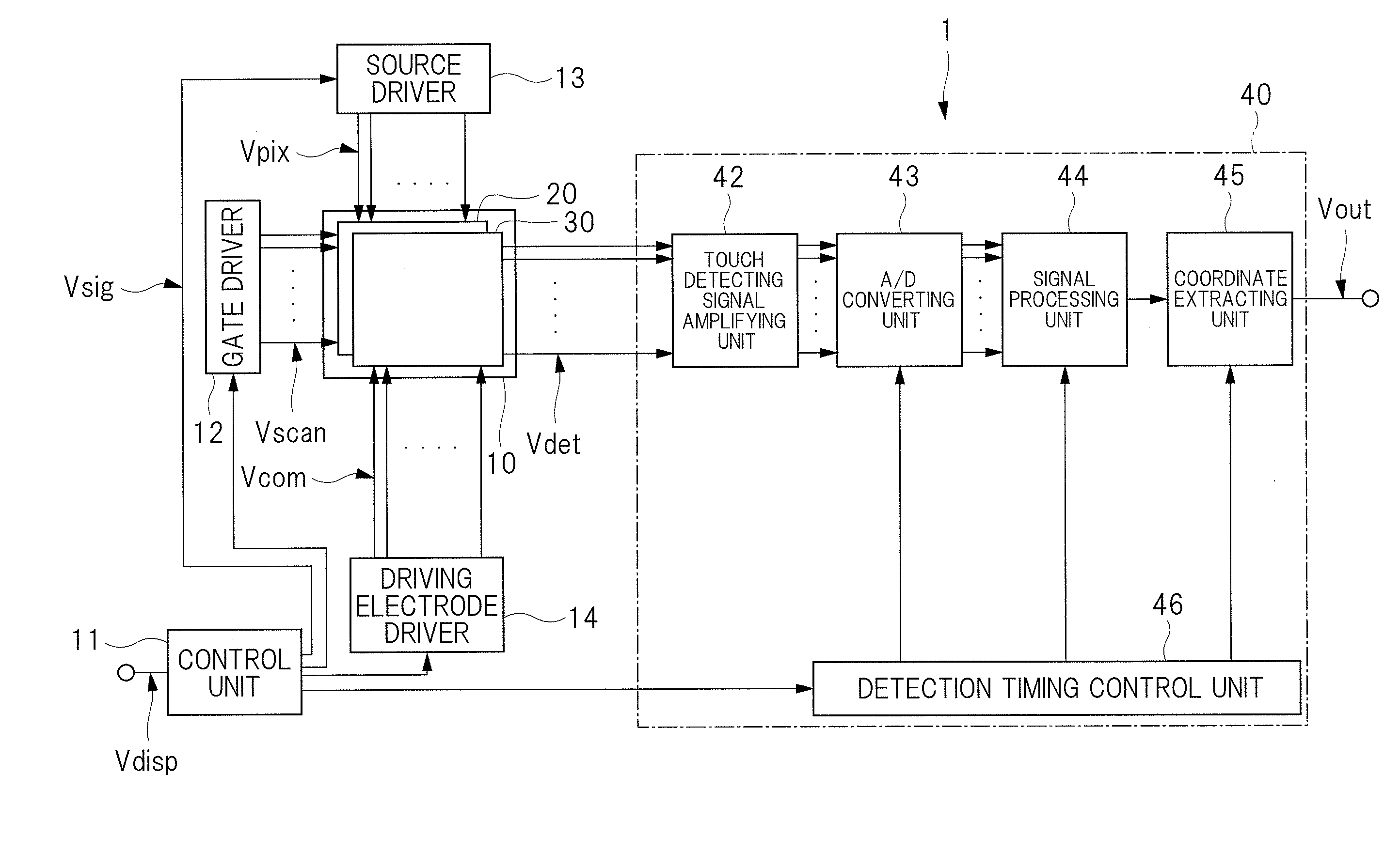
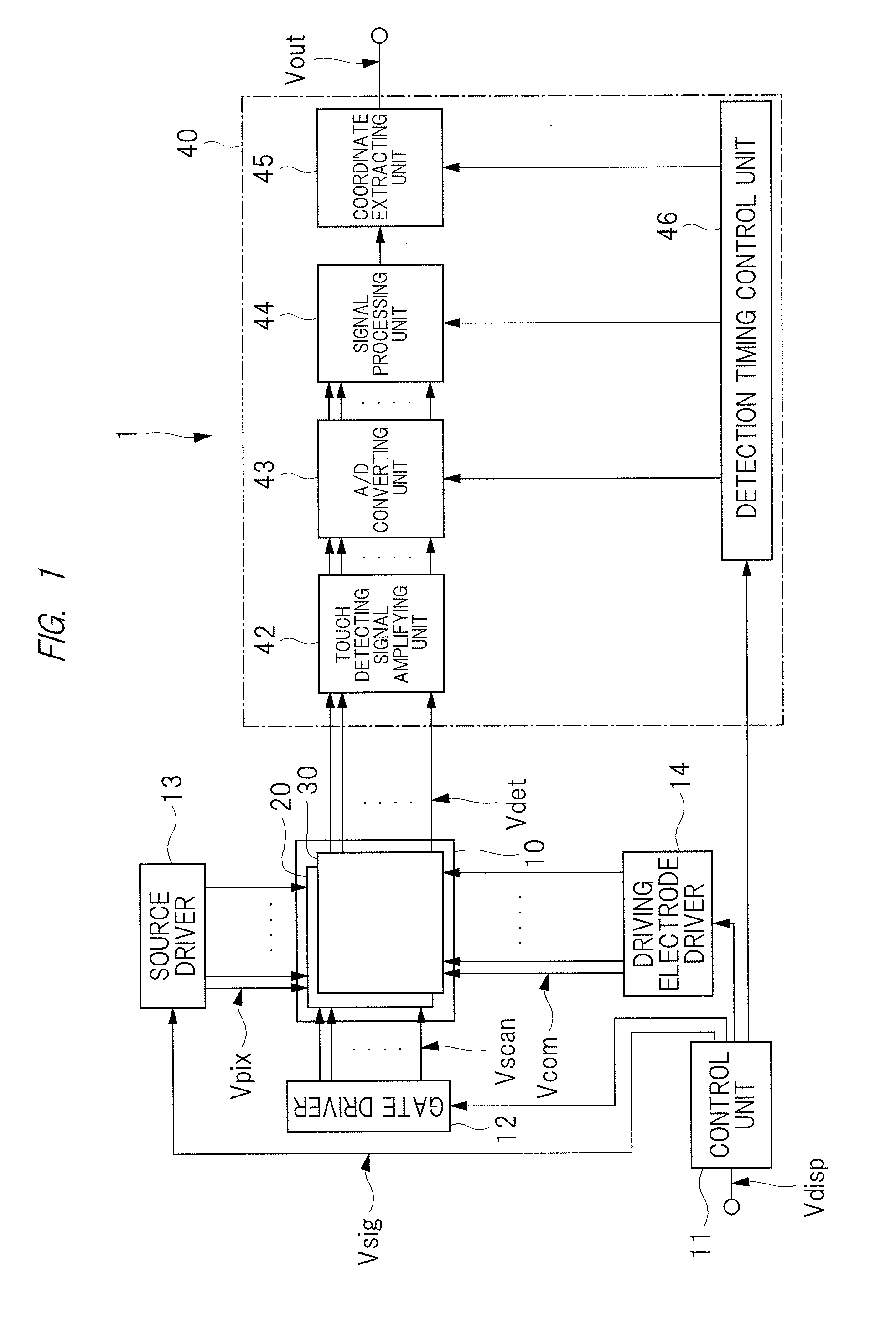
[0073]First, the overall configuration of the display device according to the present first embodiment will be described with reference to FIG. 1. FIG. 1 is a block diagram showing one configuration example of a display device according to the first embodiment.
[0074]A display device 1 includes a display device 10 with a touch detection function, a control ...
second embodiment
[0305]In the present first embodiment and the first modified example of the first embodiment, the case where driving electrodes for driving liquid crystal and touch panel are provided in the display region has been described. On the other hand, in the second embodiment, although it is an in-cell liquid crystal display device similar to the first embodiment, driving electrodes which drive the touch panel but do not drive the liquid crystal are provided apart from driving electrodes which drive the liquid crystal in the display region.
[0306]In the display device according to the second embodiment, respective components other than the driving electrodes, for example, the shape and arrangement of the detecting electrodes TDL and the dummy electrodes TDD seen in a plan view are similar to the respective components of the display device of the first embodiment and the first modified example of the first embodiment. Therefore, the descriptions thereof will be omitted.
[0307]
[0308]FIG. 31 is...
third embodiment
[0330]In the first embodiment and the second embodiment, the example in which the display device provided with a touch panel serving as an input device is applied to an in-cell liquid crystal display device with a touch detection function has been described. Meanwhile, in the third embodiment, the example in which the display device provided with a touch panel serving as an input device is applied to an on-cell liquid crystal display device with a touch detection function will be described. Note that an on-cell liquid crystal display device with a touch detection function indicates a liquid crystal display device with a touch detection function in which neither the driving electrodes nor the detecting electrodes included in the touch panel are incorporated in the liquid crystal display device.
[0331]Note that the display device of the third embodiment can be applied to on-cell display devices in which an input device is provided for various display devices such as an organic EL displ...
PUM
 Abstract
Description
Claims
Application Information
 - Generate Ideas
- Intellectual Property
- Life Sciences
- Materials
- Tech Scout
- Unparalleled Data Quality
- Higher Quality Content
- 60% Fewer Hallucinations
Browse by: Latest US Patents, China's latest patents, Technical Efficacy Thesaurus, Application Domain, Technology Topic, Popular Technical Reports.
© 2025 PatSnap. All rights reserved.Legal|Privacy policy|Modern Slavery Act Transparency Statement|Sitemap|About US| Contact US: help@patsnap.com