Organic electroluminescent element and lighting device

a technology of organic el elements and lighting devices, which is applied in the direction of electroluminescent light sources, organic semiconductor devices, thermoelectric devices, etc., can solve the problems of insufficient control of the white light emitted from the three light emitting layers (red, blue, green) in order to obtain high color rendering properties, and the organic el element according to the related art does not have a sufficient performance as a light source of a lighting device, so as to achieve high color rendering properties

Active Publication Date: 2015-07-23
XIANYANG CHVT NEW DISPLAY TECH CO LTD
View PDF2 Cites 12 Cited by
  • Summary
  • Abstract
  • Description
  • Claims
  • Application Information

AI Technical Summary

Benefits of technology

[0044]As described above, according to the invention, it is possible to provide an organic electroluminescent element that can obtain white light with high color rendering properties and a lighting device including the organic electroluminescent element.

Problems solved by technology

However, in the organic EL element according to the related art, the emission spectrum of the white light emitted from the three (red, blue, green) light emitting layers is not sufficiently controlled in order to obtain high color rendering properties.
That is, the organic EL element according to the related art does not have a sufficient performance as a light source of a lighting device.

Method used


Image

  • Organic electroluminescent element and lighting device
  • Organic electroluminescent element and lighting device
  • Organic electroluminescent element and lighting device

Examples


example 1

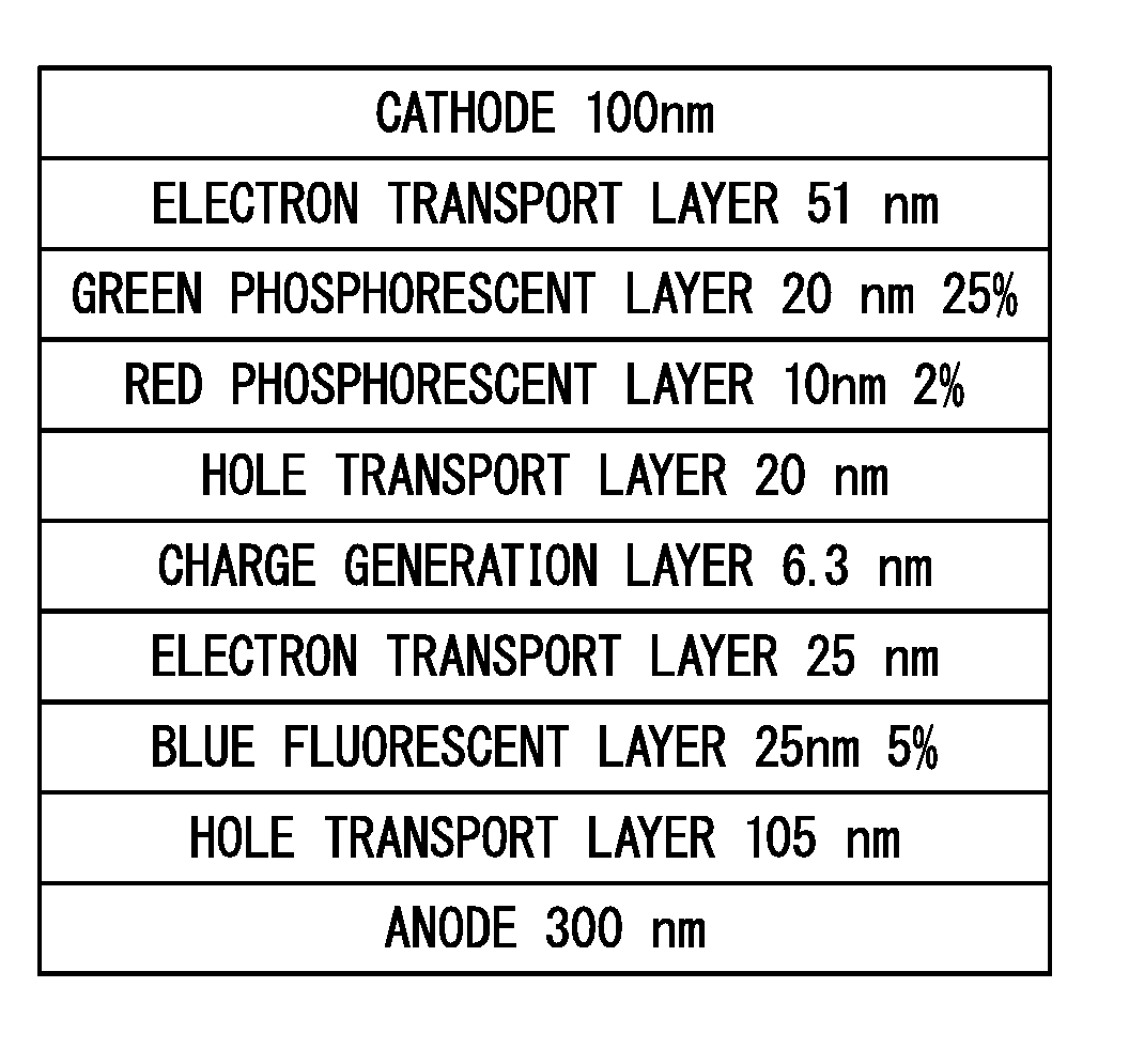
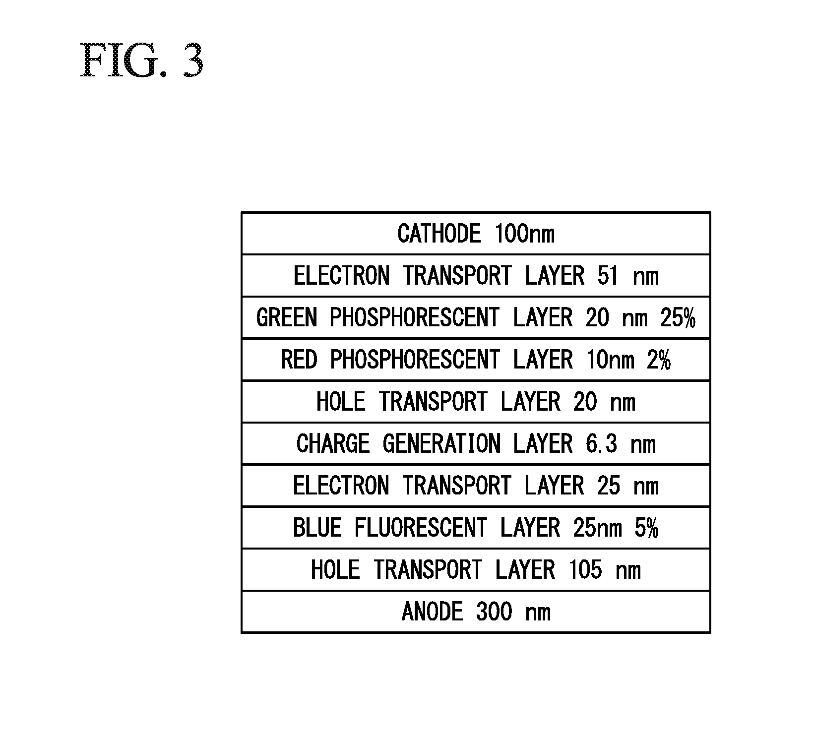
[0104]In Example 1, an organic EL element having an element structure shown in FIG. 3 was manufactured. Specifically, first, a soda lime glass substrate which had a thickness of 0.7 mm and on which an ITO film having a thickness of 300 nm, a width of 2 mm, and a sheet resistance of about 10 Ω / □ was formed was prepared. Then, ultrasonic cleaning was performed on the substrate for 5 minutes with a neutral detergent, ion-exchange water, acetone, and isopropyl alcohol. Then, spin-drying and UV / O3 treatment were sequentially performed on the substrate.

[0105]Then, deposition crucibles (made of tantalum or alumina) of a vapor deposition apparatus were filled with materials forming the layers shown in FIG. 3. Then, the substrate was set in the vapor deposition apparatus. Power was supplied to heat the deposition crucibles in a reduced pressure atmosphere with a degree of vacuum of 1×10⁻⁴ Pa or less and each layer was deposited with a predetermined thickness at a deposition speed of 0.1 nm / s...

example 2

[0108]In Example 2, an organic EL element having an element structure shown in FIG. 5 was manufactured by the same manufacturing method as that in Example 1. Then, the organic EL element according to Example 2 was evaluated by the same method as that in Example 1. The evaluation result is shown in FIG. 6.

example 3

[0109]In Example 3, an organic EL element having an element structure shown in FIG. 7 was manufactured by the same manufacturing method as that in Example 1. Then, the organic EL element according to Example 3 was evaluated by the same method as that in Example 1. The evaluation result is shown in FIG. 8.


PUM


Abstract

Provided is an organic electroluminescent element that can obtain white light with excellent color rendering properties and is particularly suitable for a light source of a lighting device. The organic electroluminescent element includes a plurality of light emitting units that are provided between a cathode and an anode and include at least a light emitting layer made of an organic compound. White light emitted from the plurality of light emitting units has a continuous emission spectrum (S) in a wavelength range of at least 380 nm to 780 nm. The emission spectrum (S) includes one peak wavelength (p1) in a red wavelength range (R) of 600 nm to 640 nm, one peak wavelength (p2) in a green wavelength range G of 500 nm to 540 nm, and two peak wavelengths (p3) and (pa) in a blue wavelength range B of 440 nm to 490 nm.

Description

TECHNICAL FIELD[0001]The present invention relates to an organic electroluminescent (EL) element and a lighting device.[0002]Priority is claimed on Japanese Patent Application No. 2012-144789, filed Jun. 27, 2012, the content of which is incorporated herein by reference.BACKGROUND ART[0003]An organic EL element is a self-luminous element in which a light emitting layer made of an organic compound is provided between a cathode and an anode that are opposite to each other. When a voltage is applied between the cathode and the anode, light is emitted by excitations which are generated by the recombination of electrons which are injected from the cathode to the light emitting layer and holes which are injected from the anode to the light emitting layer in the light emitting layer.[0004]Tang et al. in Eastman Kodak Company succeeded in developing the following structure in order to improve the efficiency of an organic EL element: organic compounds with different carrier transport propert...

Claims


Application Information

Patent Timeline
Patent Type & Authority Applications(United States)
IPC IPC(8): H01L51/50
CPCH01L51/504H01L51/5016H01L2251/5376H01L51/5092H01L2251/5361H01L51/5072H05B33/14H10K50/131H10K2101/27H10K50/13H10K50/11H10K50/16H10K50/171H10K2101/10
Inventor MORIMOTO, MITSURUTANAKA, JUNICHIMORI, KOICHI
Owner XIANYANG CHVT NEW DISPLAY TECH CO LTD
Why Eureka
Try Eureka