
Module carrier for battery cells and method for producing the module carrier, and battery module, battery pack, battery and battery system

Active Publication Date: 2015-07-23
ROBERT BOSCH GMBH
View PDF9 Cites 20 Cited by
  • Summary
  • Abstract
  • Description
  • Claims
  • Application Information

AI Technical Summary

Benefits of technology

The invention allows for better protection and holding of battery cells, which improves their mechanical performance. It also simplifies the design of the module carrier, reduces components, increases variety and scalability, and reduces costs. The module carrier can be designed to guide the battery cells along two sides, ensuring secure fixation and connection. The battery cells can also be reliably spaced from the cell terminals, preventing contact and facilitating installation.

Problems solved by technology

The battery systems have to meet very stringent requirements with regard to the useable energy content, the charging / discharging efficiency, the reliability, the service life and the undesirable loss in capacity due to frequent partial discharging.
In this case, irreversible damage to the battery cells may also occur.
In this case, irreversible damage to the battery cells can likewise occur.
At greater temperature differences, various regions of a battery cell or various battery cells of a battery module or of a battery can be subjected to different loadings or can even be (partially) overloaded and / or damaged.
Furthermore, because of temperature differences and / or temperature changes, there is a risk of condensation water forming in the battery.
The damage can lead to accelerated ageing of the battery cells or to thermal runaway of the battery cells, which constitutes a risk for people and the environment.
On account of the internal resistance of the battery cells, these short peak loadings lead to a significant heating of the battery cells.
The efficiency of the battery cells during charging and discharging is very high (approximately 95%); nevertheless, the waste heat which arises in the process is not negligible.
At a traction power of, for example, 60 KW, a loss of 5% results in a loss of power of 3 KW.
Furthermore, for example in the summer months or in warmer regions, external temperatures which may be 40° C. and more may lie outside the permissible temperature range, and therefore, without cooling, the battery cells cannot achieve a service life of, for example, ten years.
Secondly, at low temperatures, the battery cells may have to be heated up to a minimum temperature.

Method used


Image

  • Module carrier for battery cells and method for producing the module carrier, and battery module, battery pack, battery and battery system
  • Module carrier for battery cells and method for producing the module carrier, and battery module, battery pack, battery and battery system
  • Module carrier for battery cells and method for producing the module carrier, and battery module, battery pack, battery and battery system

Examples


Embodiment Construction

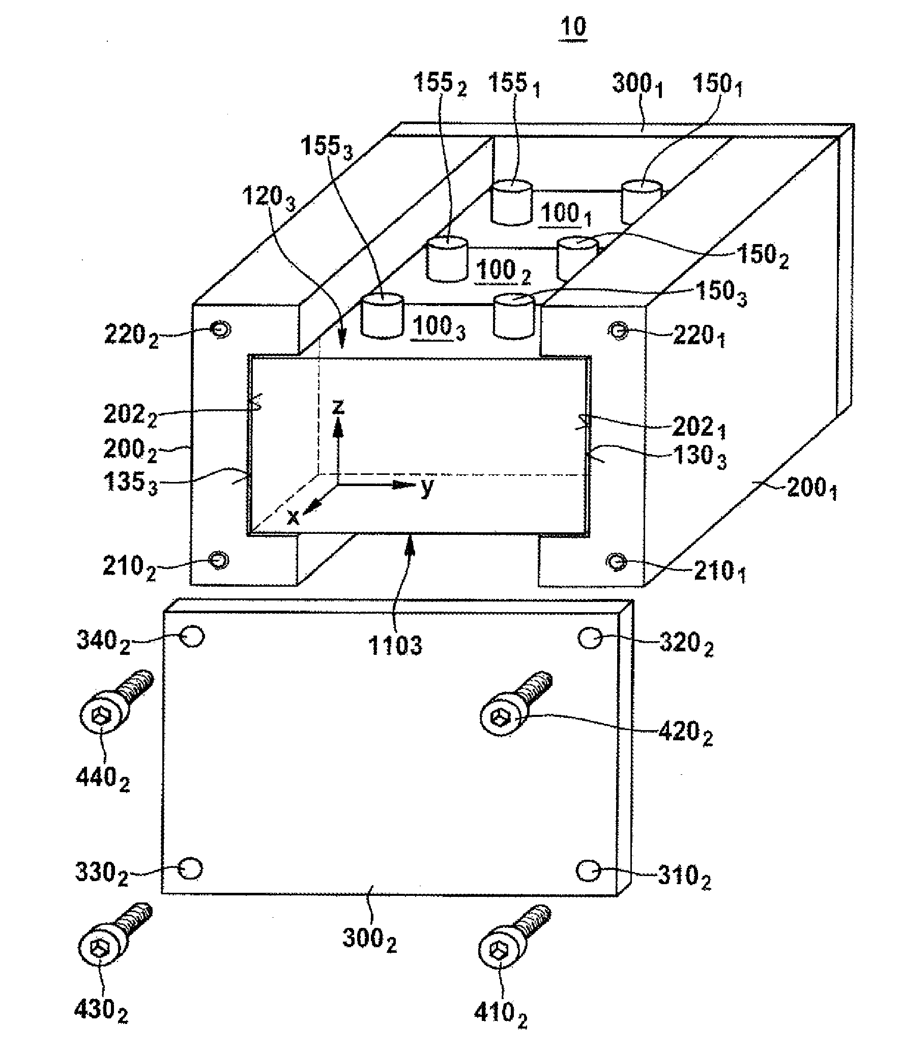
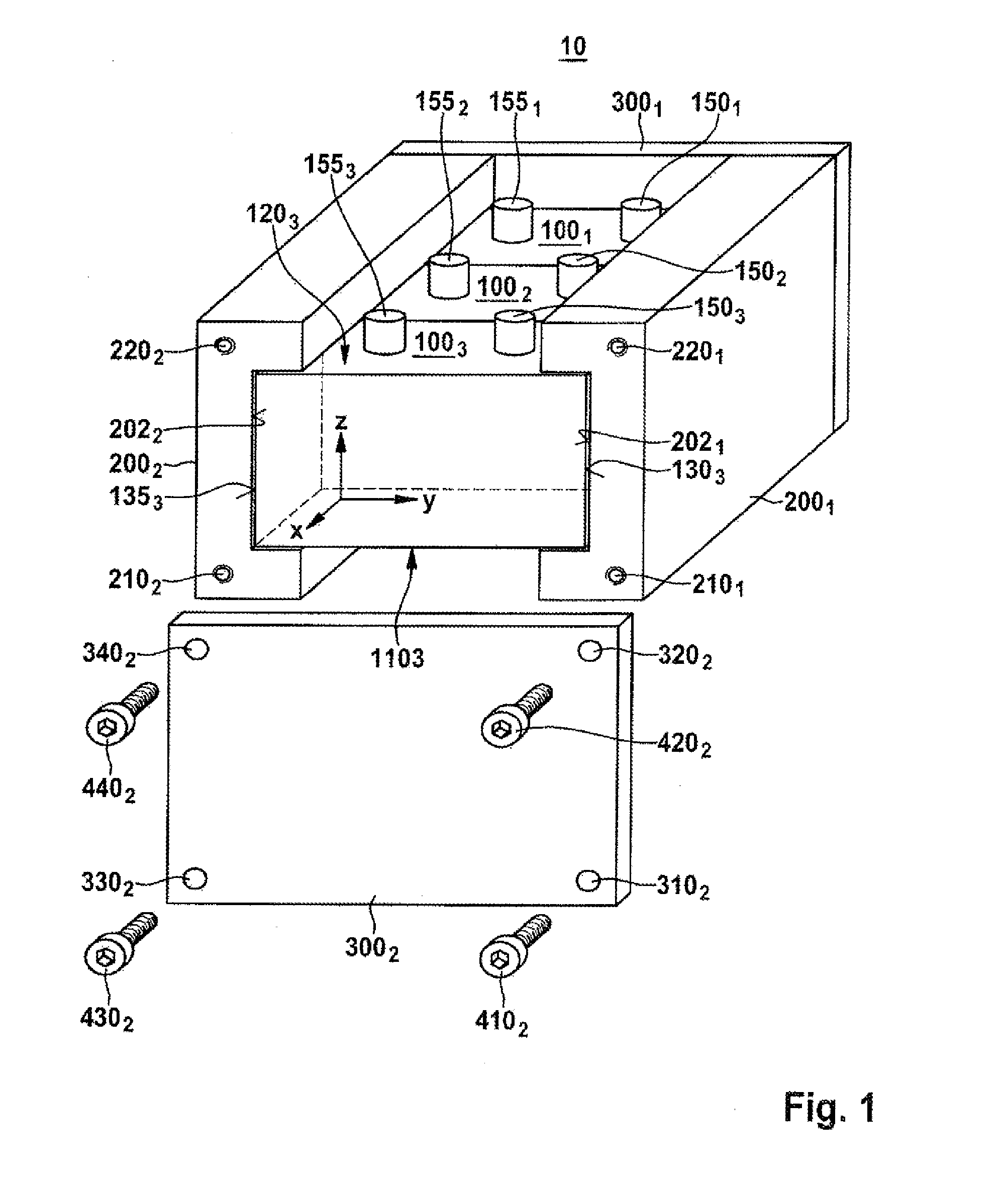
[0043]FIG. 1 shows a schematic perspective view of an open battery module 10 according to one embodiment of the invention.

[0044]The battery module 10 comprises a multiplicity of battery cells 1001, 1002, 1003, for example two, three, four or more battery cells. As shown by way of example in FIG. 1, the battery cells 1001, 1002, 1003 are oriented in a first direction in space (x) such that the longitudinal sides thereof, which are oriented in a second direction in space (y) perpendicular to the first direction in space (x), run parallel to one another. A third direction in space (z) which is perpendicular to the first direction in space (x) and second direction in space (y) denotes the vertical direction of the battery cells 1001, 1002, 1003 during use according to the specifications.

[0045]The battery cells 1001, 1002, 1003 can be prismatic, for example cuboidal, and can each comprise a cell housing and a cell cover with in each case two electric cell terminals 1501, 1551, 1502, 1552...


PUM


Abstract

A module carrier (20; 20′; 30; 40; 50; 60; 70; 80; 90; 92; 94) for battery cells (1001, 1002, 1003), characterized by: a first carrier device (2001) and a second carrier device (2002), which is arranged opposite the first carrier device (2001), for carrying the battery cells (1001, 1002, 1003), and a first connecting device (3001) and a second connecting device (3002), which is arranged opposite the first connecting device (3001), in each case for connecting the first carrier device (2001) and the second carrier device (2002).

Description

BACKGROUND OF THE INVENTION[0001]The invention relates to a module carrier for battery cells, and to a method for producing the module carrier, and to a battery module, a battery pack, a battery and a battery system. The invention furthermore relates to a vehicle, in particular a motor vehicle, such as an electric motor vehicle or hybrid vehicle, with the module carrier, the battery module, the battery or the battery system.[0002]It is foreseeable that both in the case of stationary applications, for example in wind power installations, and in the case of mobile applications, for example in the case of electric motor vehicles (electric vehicles, EV) or hybrid vehicles (hybrid electric vehicles, HEV), use will increasingly be made of novel battery systems, for example with lithium-ion storage batteries or nickel-metal hybrid storage batteries, as rechargeable energy accumulators.[0003]The battery systems have to meet very stringent requirements with regard to the useable energy conte...

Claims


Application Information

Patent Timeline
IPC IPC(8): H01M2/10H01M50/202H01M50/209H01M50/224H01M50/227H01M50/262
CPCH01M2/1005H01M2/1094H01M2220/20H01M10/625H01M10/6567H01M10/613H01M50/227H01M50/262H01M50/209H01M50/224H01M10/6556H01M10/617Y02E60/10H01M50/256H01M50/24
Inventor WONDRACZEK, LUTZ
Owner ROBERT BOSCH GMBH
Learn More