Semiconductor Device

a technology of semiconductor devices and connecting parts, which is applied in the direction of coupling device connections, electrical apparatus casings/cabinets/drawers, and association of printed circuit non-printed electric components, etc., can solve the problems of thermal disadvantage of semiconductor devices, and achieve the effect of easy carrying of current and small degree of rotation of the external terminal connecting portion

Active Publication Date: 2015-07-23
TOYOTA IND CORP
View PDF2 Cites 7 Cited by
  • Summary
  • Abstract
  • Description
  • Claims
  • Application Information

AI Technical Summary

Benefits of technology

[0010]In this aspect, each of the connecting terminals includes the external terminal connecting portion, having the end surface to connect the external terminal thereto and located at the second principal surface side of the second circuit board faces, and the substrate-fixed portion which is securely connected to the first circuit board. The external terminal connecting portion and the substrate-fixed portion are eccentrically located when viewed from the direction in which the first circuit board and the second circuit board are opposed. Thus, the connecting terminal can be small-sized and therefore the mount region of the connecting terminal on the circuit board needs not be large. At least one of the connecting terminals is provided with the reduced sectional area portion, having the sectional area smaller than the area of the top end surface of the external terminal connecting portion, in the region of the external terminal connecting portion from the seal attachment portion to the end in the opposite side of the end surface, which region opposes the plurality of electronic components arranged on the second circuit board. Thus, by allowing the top end surface of the external terminal connecting portion to overlap a portion of the electronic component adjoining the reduced sectional area portion when viewed from the direction in which the first circuit board and the second circuit board are opposed, the electronic component can be arranged close enough to the external terminal connecting portion. Electronic components around the connecting terminal can thus be compactly mounted on the circuit board.
[0011]In this aspect, the external terminal connecting portion may include a projecting portion that projects from the reduced sectional area portion toward the substrate-fixed portion. In this case, the external terminal connecting portion can carry current easily because a large current-carrying area is sufficiently secured thereby.
[0012]In this aspect, a rim of the top end surface of the external terminal connecting portion may have a plurality of straight regions and a shape of the hole may correspond to a shape of the top end surface. When the substrate-fixed portion is secured to a substrate by a single point, the external terminal connecting portion might rotate about the substrate-fixed portion when the external terminal is connected to the top end surface of the external terminal connecting portion by securing with a bolt. If the external terminal connecting portion rotates about the substrate-fixed portion, the portion of the external terminal connecting portion including the end surface might abut the inner wall of the case forming the hole. Since the rim of the top end surface of the external terminal connecting portion has a plurality of straight regions, when the portion of the external terminal connecting portion abuts the inner wall of the case, the end of the straight region abuts the inner wall of the case. As such, the degree of motion (degree of rotation) of the external terminal connecting portion can be kept small. Consequently, even when the substrate-fixed portion is secured to the substrate by a single point, the accuracy of positioning the external terminal connecting portion can be secured.

Problems solved by technology

When the top end surface area is small, therefore, the cylinder portion (end portion) is likely to generate heat which is thermally disadvantageous to the semiconductor device.

Method used


Image

  • Semiconductor Device
  • Semiconductor Device
  • Semiconductor Device

Examples


Embodiment Construction

[0024]The embodiment of the present invention will be described in detail referring to the attached drawings. In the description, the same component or the component having the same function is denoted with the same reference sign and repeated description thereof will be omitted. Dimensional ratios in each drawing may be different from the actual dimensional ratios.

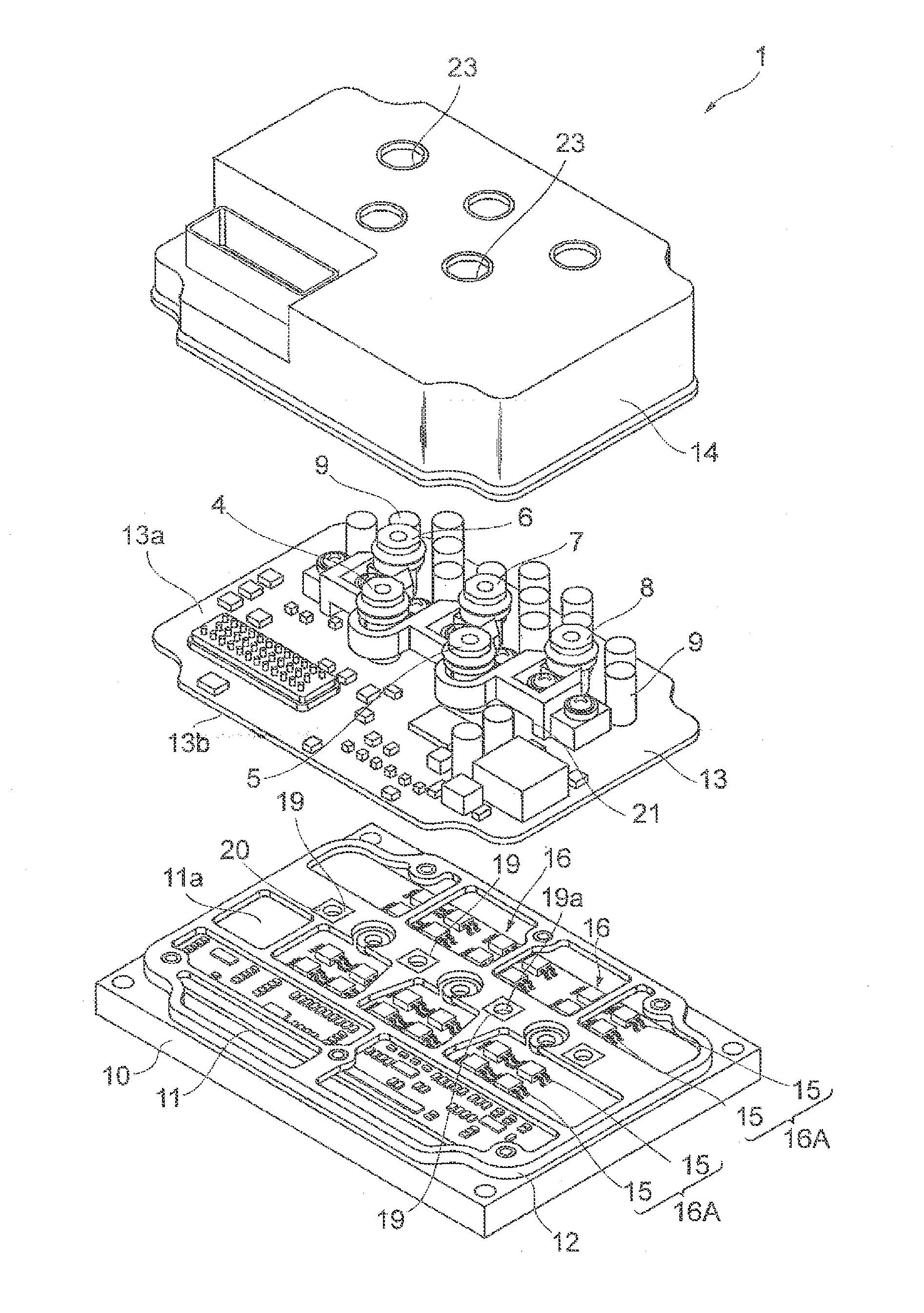
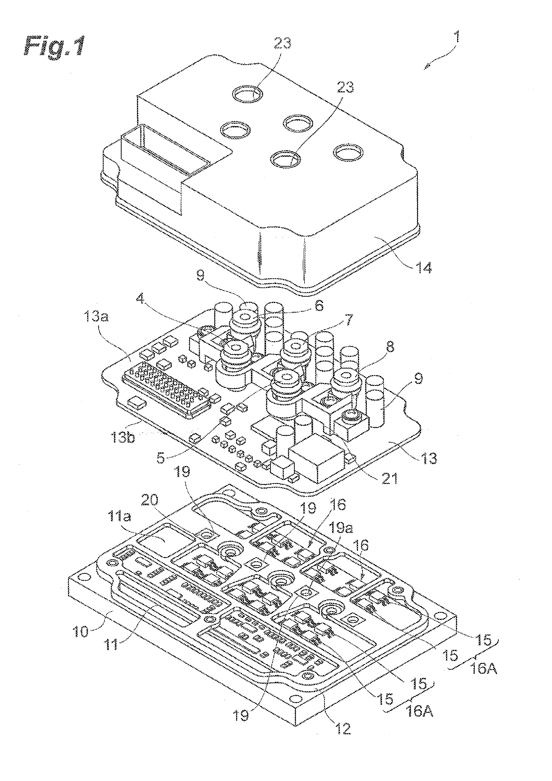
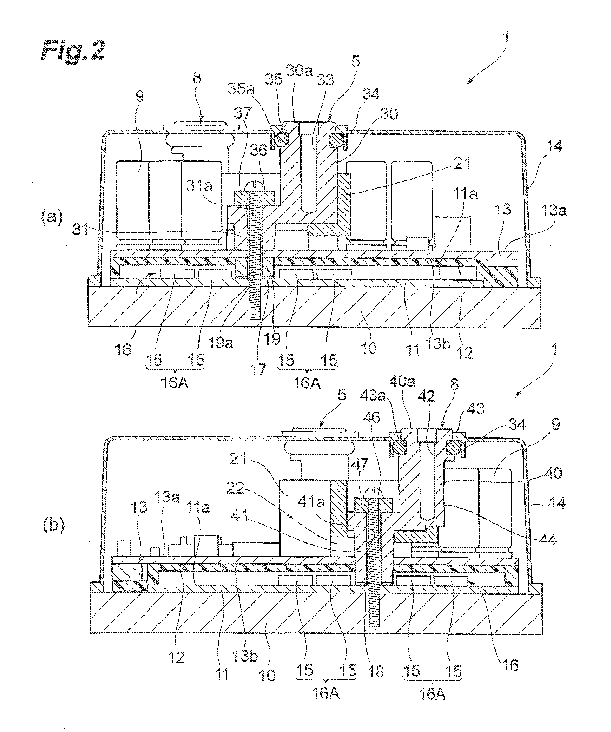
[0025]FIG. 1 is an exploded perspective view illustrating an inverter device according to the embodiment. FIG. 2 is sectional views of the inverter device illustrated in FIG. 1. In FIG. 2, (a) is a sectional view taken along the line IIA-IIA in FIG. 4 and (b) is a sectional view taken along the line IIB-IIB in FIG. 4. The inverter device 1 of the embodiment is, for example, a three-phase inverter device for driving a three-phase AC motor.

[0026]FIG. 3 is a circuit diagram of the inverter device 1. As illustrated in FIG. 3, the inverter device 1 includes a main circuit 2, a control circuit 3 for controlling the main circuit...


PUM


Abstract

A connecting terminal includes an external terminal connecting portion, having an end surface to connect an external terminal thereto and located at a second principal surface side of a second circuit board faces, and a substrate-fixed portion which is securely connected to a first circuit board. A seal attachment portion is provided on a portion of the external terminal connecting portion including the end surface to attach thereto a seal member to seal a gap between the portion and the case. The connecting terminal includes a reduced sectional area portion having a sectional area smaller than an area of the top end surface in a region close to a plurality of electronic components arranged on the second circuit board on the external terminal connecting portion. The reduced sectional area portion is provided from the seal attachment portion to an end in the opposite side of the end surface.

Description

BACKGROUND OF THE INVENTION[0001]1. Field of the Invention[0002]The present invention relates to a semiconductor device.[0003]2. Related Background Art[0004]There are known semiconductor devices such as a semiconductor device discussed in JP Registered Utility Model Publication No. 3173512. The semiconductor device discussed in JP Registered Utility Model Publication No. 3173512 includes a main circuit board mounted with a plurality of semiconductor elements composing a main circuit, a capacitor substrate which is closely arranged on the main circuit board and mounted with a plurality of capacitors, and a control circuit board which is arranged on the capacitor substrate with a distance provided in between and mounted with a control circuit controlling the main circuit. A positive input terminal, a negative input terminal, and three output terminals are mounted on the main circuit board. Each terminal includes a bus bar extending from the main circuit board and a cylinder portion wh...

Claims


Application Information

Patent Timeline
Patent Type & Authority Applications(United States)
IPC IPC(8): H05K5/00H05K1/18H05K1/14
CPCH05K5/0026H05K2201/10537H05K1/181H05K1/144H01R12/515H01R13/5202H01R13/6315H02M7/003H05K3/325H05K2201/09063H05K7/14322H05K7/14329H05K7/1432
Inventor KONTANI, KAZUYOSHIDOJIRI, ATSUSHI
Owner TOYOTA IND CORP
Why Eureka
Try Eureka