Scale suppression apparatus, geothermal power generation system using the same, and scale suppression method
a technology of scale suppression and scale, which is applied in the direction of mechanical equipment, mechanical power devices, machines/engines, etc., can solve the problems of not being economical and an expensive agent of chelating agent, and achieve the effect of enhancing the effect of agglutinating scale, suppressing the generation of amorphous silica, and increasing the reaction rate of silica polymerization
- Summary
- Abstract
- Description
- Claims
- Application Information
AI Technical Summary
Benefits of technology
Problems solved by technology
Method used
Image
Examples
first embodiment
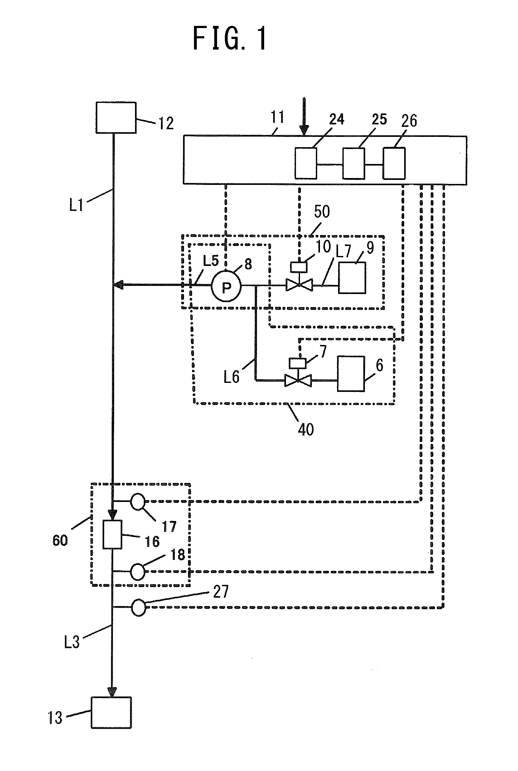
[0037]FIG. 1 is a schematic configuration view of a scale suppression apparatus according to a first embodiment of the present disclosure. The scale suppression apparatus according to the first embodiment of the present disclosure is an apparatus of suppressing the generation of silica-based scale and calcium-based scale occur in influent water containing at least a silica component and a calcium component, and includes a pipe arrangement L1, a first addition unit 40, a second addition unit 50, a scale detection unit 60, a pipe arrangement L3, a pH meter 27, and a controller 11.
[0038]The pipe arrangement L1 leads the influent water that has flowed from an influent water inlet 12 to the scale detection unit 60, and one end of the pipe arrangement L1 is connected to an inlet part of the scale detection unit 60.
[0039]The first addition unit 40 injects liquid containing a chelating agent and alkaline agent (i.e., alkaline liquid) into the influent water flowing through the pipe arrangem...
second embodiment
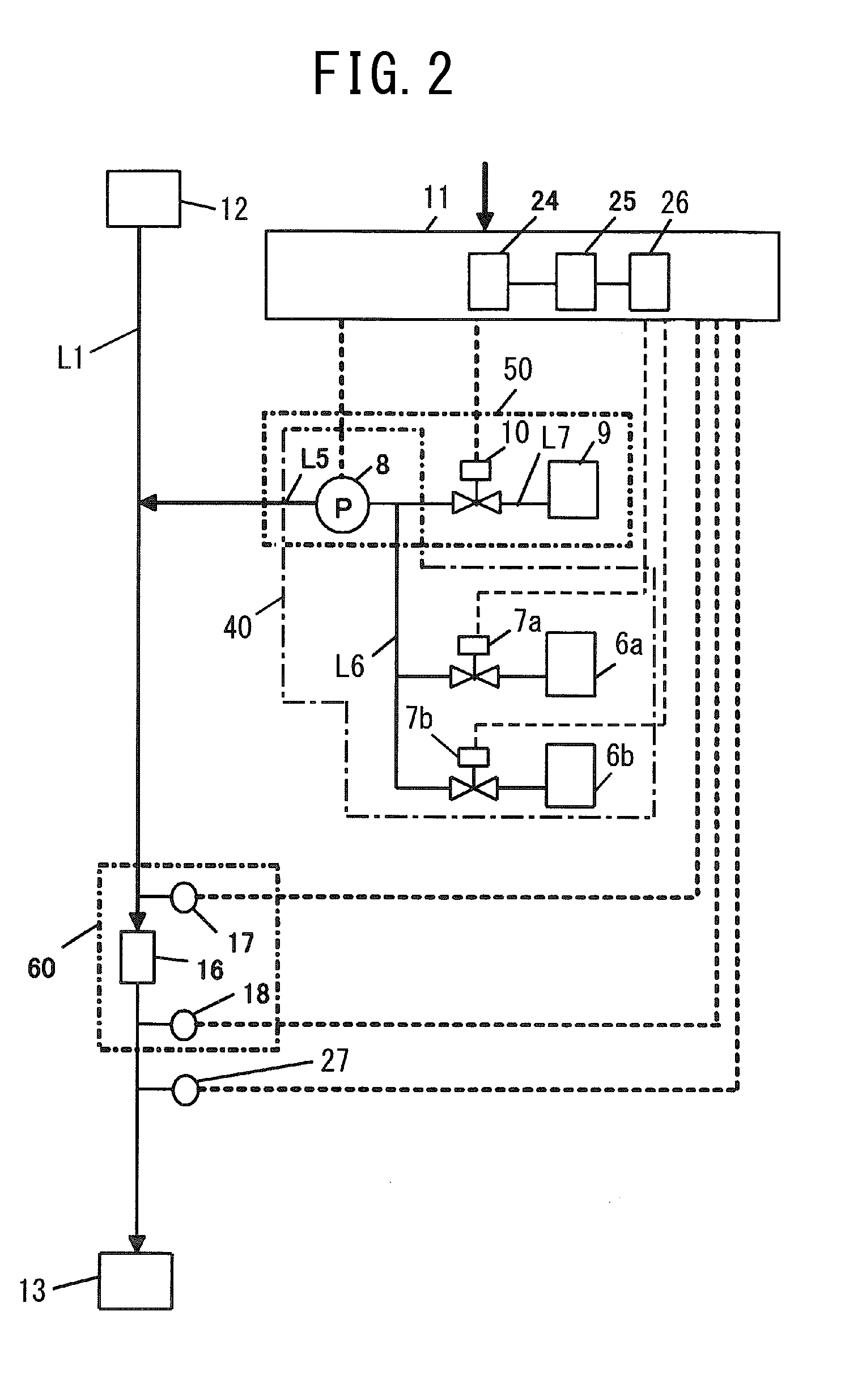
[0060]In the above-described first embodiment, the first addition unit configured to add the liquid containing the chelating agent and alkaline agent into the pipe arrangement L1 through which the influent water flows includes the tank 6 configured to reserve the liquid containing the chelating agent and alkaline agent, the pump 8 configured to inject the liquid reserved in the tank 6 into the pipe arrangement L1, the pipe arrangement L6 configured to connect the outlet port of the tank 6 and the inlet port of the pump 8, the pipe arrangement L5 configured to connect the exhaust port of the pump 8 and the injection port of the pipe arrangement L1, and the valve 7 arranged in the pathway of the pipe arrangement L6 has been illustrated. However, the present disclosure is not limited to the above configuration. As illustrated in FIG. 2, for example, in a second embodiment, the first addition unit 40 configured to inject the liquid containing the chelating agent and alkaline agent into ...
third embodiment
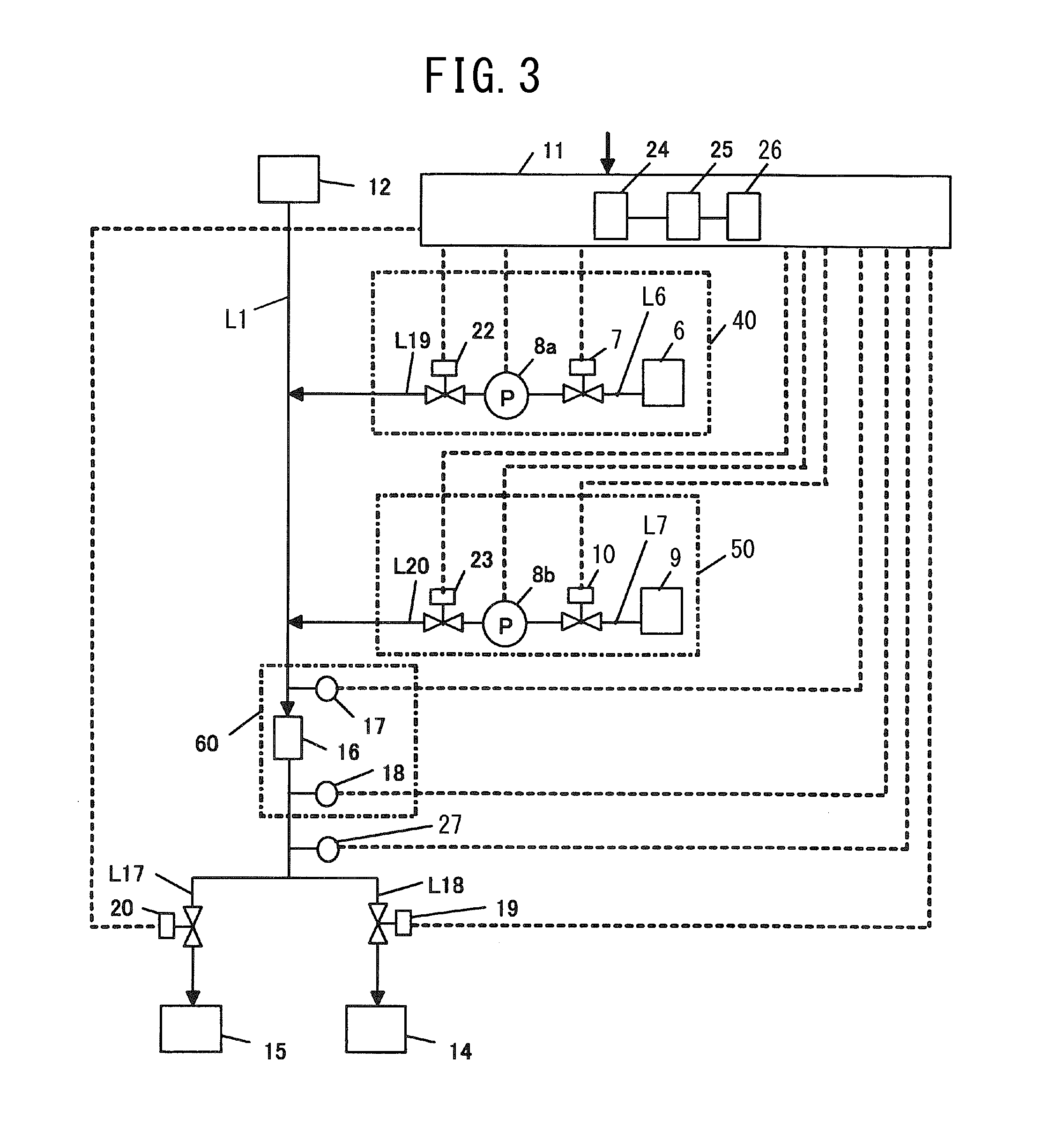
[0061]FIG. 3 is a schematic configuration view of the scale suppression apparatus according to a third embodiment of the present disclosure. The scale suppression apparatus according to the third embodiment, as illustrated in FIG. 3, includes the pipe arrangement L1, the first addition unit 40, the second addition unit 50, the scale detection unit 60, pipe arrangements L17 and L18, valves 19 and 20, the pH meter 27, and the controller 11.
[0062]The pipe arrangement L1 leads the influent water that has flowed from an influent water inlet 12 to the scale detection unit 60, and one end of the pipe arrangement L1 is connected to the inlet part of the scale detection unit 60.
[0063]The first addition unit 40 injects the liquid containing the chelating agent and alkaline agent into the influent water flowing through the pipe arrangement L1 to make the influent water higher than pH 7. The first addition unit 40 includes the tank 6 configured to reserve the liquid containing the chelating age...
PUM
| Property | Measurement | Unit |
|---|---|---|
| pH | aaaaa | aaaaa |
| pH | aaaaa | aaaaa |
| upper limit threshold | aaaaa | aaaaa |
Abstract
Description
Claims
Application Information
 - R&D
- Intellectual Property
- Life Sciences
- Materials
- Tech Scout
- Unparalleled Data Quality
- Higher Quality Content
- 60% Fewer Hallucinations
Browse by: Latest US Patents, China's latest patents, Technical Efficacy Thesaurus, Application Domain, Technology Topic, Popular Technical Reports.
© 2025 PatSnap. All rights reserved.Legal|Privacy policy|Modern Slavery Act Transparency Statement|Sitemap|About US| Contact US: help@patsnap.com


