Control of System with Gas Based Cycle

Inactive Publication Date: 2015-07-30
ENERGY TECH INST
View PDF2 Cites 43 Cited by
  • Summary
  • Abstract
  • Description
  • Claims
  • Application Information

AI Technical Summary

Benefits of technology

[0050]In one embodiment, net mass flow through the half-engine acting as an expander may be decreased (resp increased) by advancing (resp retarding) the closure of the inlet (HP) valve on the down-stroke.
[0051]In one embodiment, net mass flow through the expander may be decreased (resp increased) by advancing (resp retarding) the closure of the exhaust (LP) valve on the

Problems solved by technology

A common problem in reciprocating gas compressors is how to reduce (or change) volumetric flow rates from normal (full capacity) to a lower rate.
However, because there is a spring, these valves are highly susceptible to hitting resonant conditions which can end up destroying the valve in a short period of time.
Unfortunately the variable speed also greatly increases the likelihood that

Method used


Image

  • Control of System with Gas Based Cycle
  • Control of System with Gas Based Cycle
  • Control of System with Gas Based Cycle

Examples


Embodiment Construction

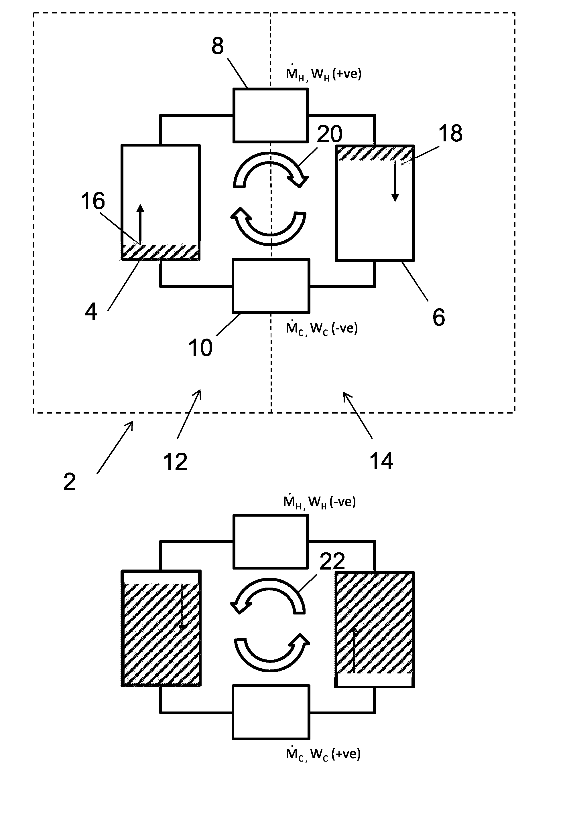
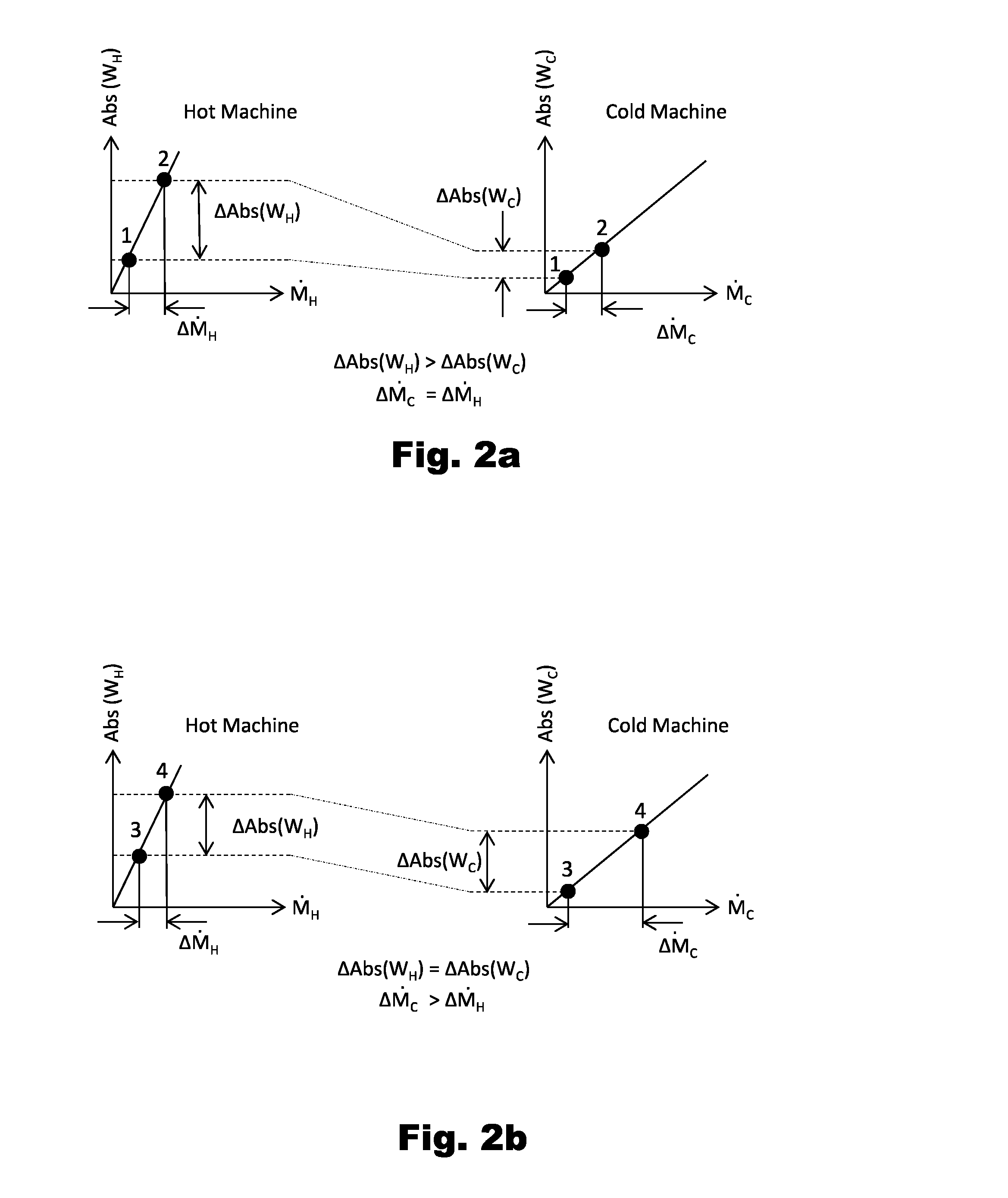
[0078]The present invention may be of application in any apparatus or system carrying out a gas based thermodynamic cycle comprising a compressor and expander, such as a heat engine or heat pump cycle, or both. The independent control of respective gas mass flow rates through the compressor and expander may be used to provide independent graduated control of two system variables, such as power and pressure type variables.

[0079]For example, an office air conditioning system or a cold-room refrigeration system operating as an open cycle heat pump using air as the working fluid is an example of such a system. Incoming air (from the external environment, or recirculated within the office or cold room) is compressed to an increased pressure and temperature. It is then passed through a heat exchanger in which it loses heat to the external environment at approximately constant pressure. The cooled high pressure air is then expanded back to atmospheric pressure and (because it has lost heat...


PUM


Abstract

System (2) for carrying out a gas based thermodynamic cycle in which a gas is compressed in at least one compressor (8) in one part of the cycle and is expanded in at least one expander (10) operating simultaneously in an upstream or downstream part of the cycle, wherein the change in absolute internal power with gas mass flow rate differs as between the compressor and the expander and wherein the system comprises a control system configured to make selective adjustments so as individually to control, either directly or indirectly, the respective gas mass flow rates through each of the compressor and expander. The system may be an energy storage system including a pumped heat energy storage system configured to provide independent graduated control of system pressure and output power by selective adjustment of the respective gas mass flow rates through each half-engine.

Description

TECHNICAL FIELD OF THE INVENTION[0001]The present invention relates to a system for carrying out a gas based thermodynamic cycle and to a method of operating such a system. In particular, it relates to an energy storage system, which may be a system for receiving and returning energy in the form of electricity (i.e. electricity storage system), especially a pumped heat electricity storage (PHES) system.BACKGROUND OF THE INVENTION[0002]Applicant's earlier Application WO 2009 / 044139 discloses a thermodynamic electricity storage system using thermal stores. In the most basic configuration, a hot store and a cold store are connected to each other by a compressor and expander (the latter is often referred to as a turbine in axial flow machinery). In a charging mode heat is pumped from one store to the other (i.e. heating the hot store and cooling the cold store) and in a discharge mode the process in the system is reversed (i.e. with the cold store being used to cool gas prior to compres...

Claims


Application Information

Patent Timeline
IPC IPC(8): F01K3/02F01K7/16F01K7/00F01K3/12
CPCF01K3/02F01K7/00F01K7/16F01K3/12F01K7/36F04B7/0076
Inventor HOWES, JONATHAN SEBASTIANMACNAGHTEN, JAMESHUNT, ROWLAND GEOFFREY
Owner ENERGY TECH INST
Why Eureka
Try Eureka