
Condenser-reboiler system and method

Active Publication Date: 2015-07-30
PRAXAIR TECH INC
View PDF2 Cites 4 Cited by
  • Summary
  • Abstract
  • Description
  • Claims
  • Application Information

AI Technical Summary

Benefits of technology

This patent discusses improvements to a condenser-reboiler module used in industrial processes. The invention includes adding impingement plates or baffle plates to enhance the dispersion of the condensing medium and minimize bypass flow. Another embodiment includes a distributor structure that radially distributes the flow of the condensing medium to disperse it to the condensing surfaces. These improvements lead to better heat exchange and more efficient operation of the module.

Problems solved by technology

While both of these configurations ensure safe operation of the oxygen vaporization process, both of these configurations also have certain disadvantages.
Other problems that diminish the thermal performance of the condenser-reboiler and, in turn, adversely affect the energy efficiency and operating costs of the cryogenic air separation unit are the accumulation of non-condensables in the main condenser-reboiler.
As indicated above, the higher bulk temperature difference between the condensing nitrogen and boiling oxygen translates to a higher pressure requirement for the incoming nitrogen vapor which ultimately results in higher compression power and associated costs for the air separation unit.
In addition, since the non-condensables tend to aggregate or accumulate on the heat transfer surfaces of the main condenser-reboiler where the bulk vapor velocities are lower, the high concentration zones of non-condensables in many current designs are dispersed throughout the main condenser-reboiler such that it becomes difficult to collect and remove them, which for some of the non-condensables such as neon which has significant commercial value, it cannot be recovered in a cost effective manner.

Method used


Image

  • Condenser-reboiler system and method
  • Condenser-reboiler system and method
  • Condenser-reboiler system and method

Examples


Embodiment Construction

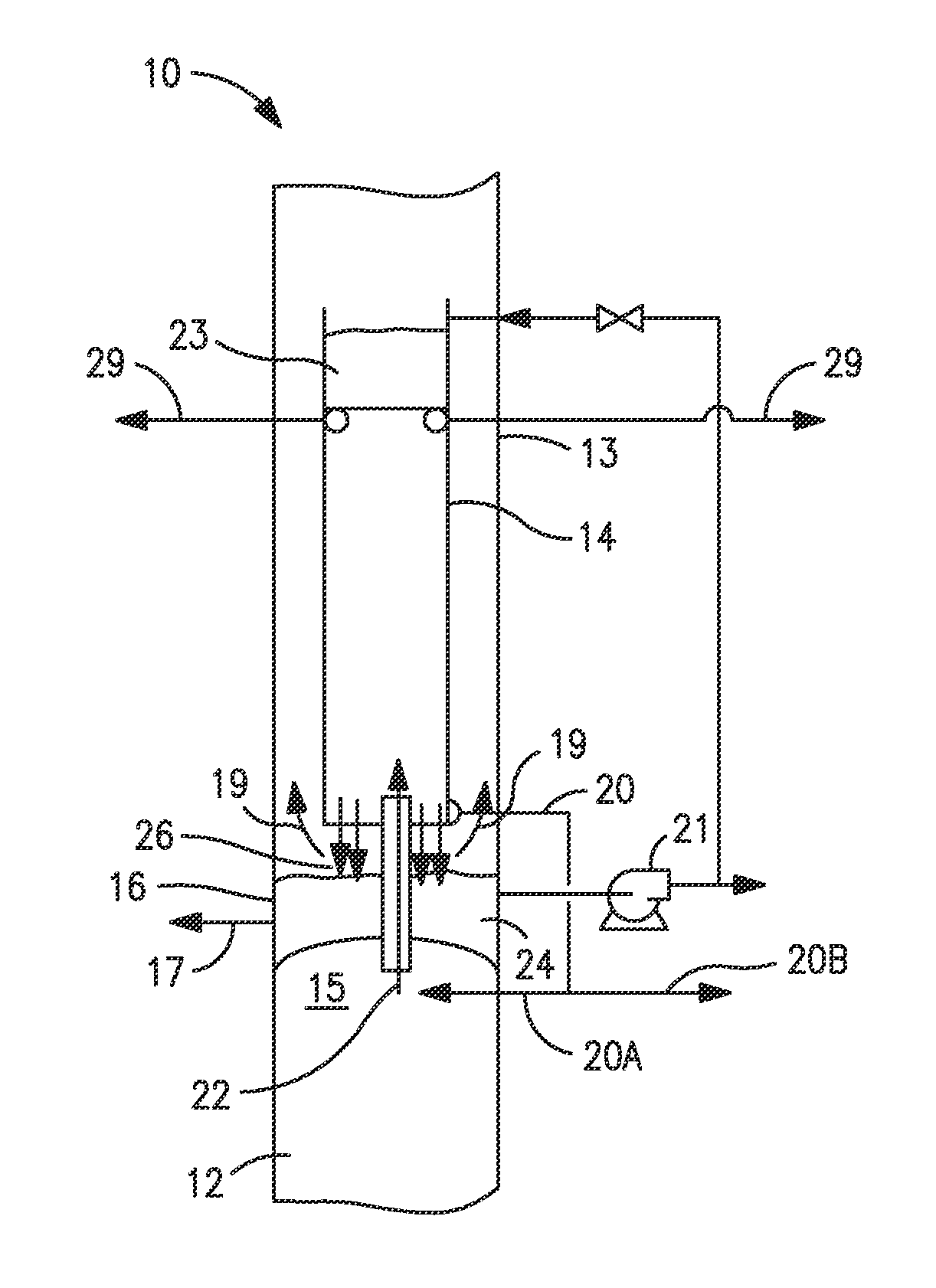
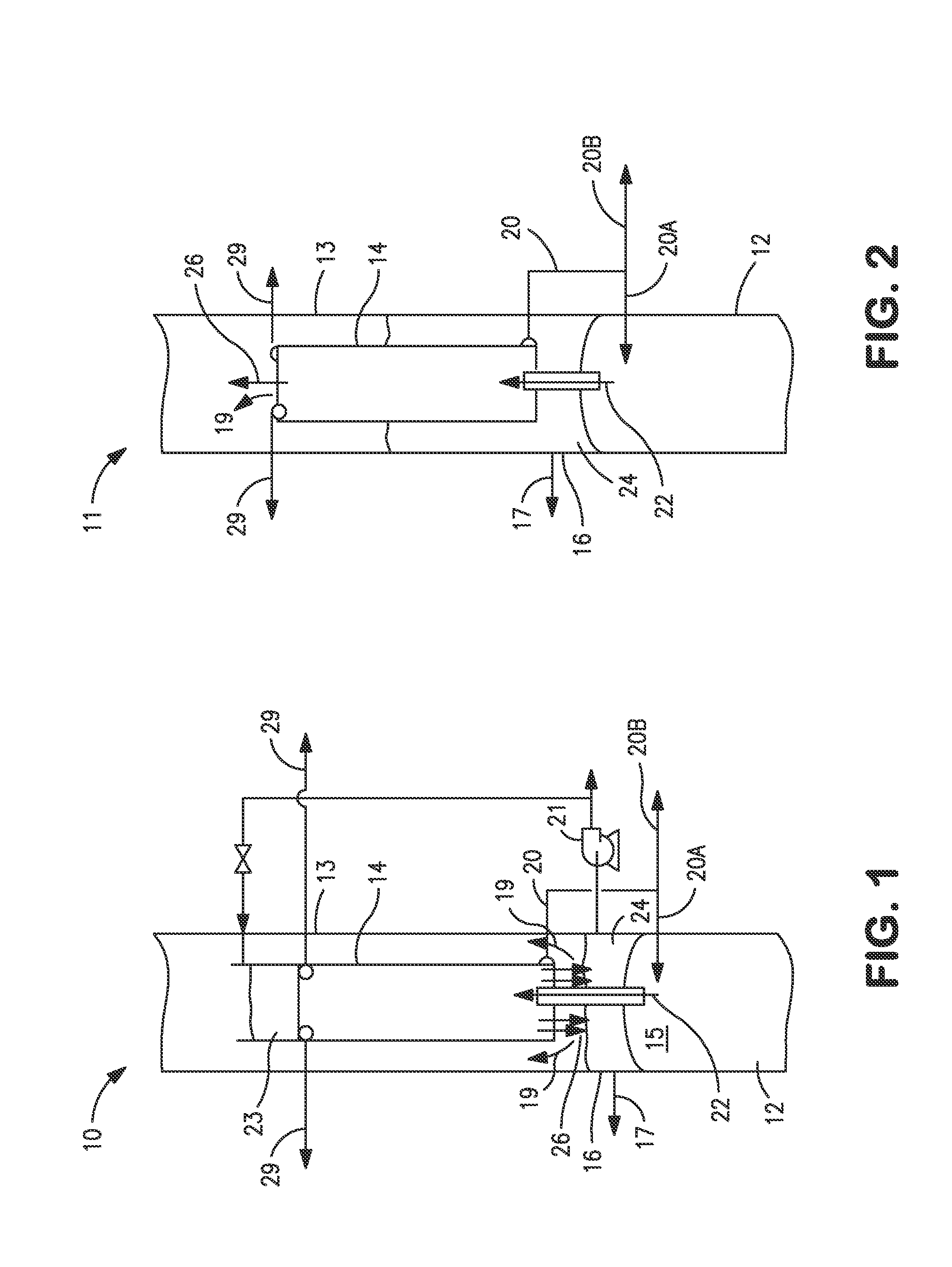
[0033]Turning now to FIG. 1 and FIG. 2, there is shown a schematic illustration of a distillation column arrangement in an air separation unit depicting a typical condenser-reboiler module with up-flow of the condensing medium such as nitrogen vapor or air vapor. FIG. 1 shows the present condenser-reboiler with up-flow of the nitrogen vapor configured as a downflow type heat exchanger whereas FIG. 2 shows the present condenser-reboiler with up-flow of the nitrogen vapor configured as a thermosyphon type heat exchanger.

[0034]The distillation column arrangements 10 and 11 each have a higher pressure distillation column 12 and a lower pressure distillation column 13 and a main condenser-reboiler module 14 coupling the higher and lower pressure distillation columns in a heat transfer relationship. The distillation column arrangements 10 and 11 are specifically designed to conduct a distillation process in connection. Distillation column arrangements 10 and 11 are used in the separation ...


PUM


Abstract

A system and method for the concurrent condensation of a nitrogen-rich vapor and vaporization of an oxygen-rich liquid in a distillation column based air separation unit is provided. The disclosed system includes a condenser-reboiler heat exchanger located between a lower pressure column and a higher pressure column and configured to condense a nitrogen-rich vapor from the higher pressure column and partially vaporize an oxygen-rich liquid from the lower pressure column. Within the condenser-reboiler heat exchanger, the nitrogen-rich vapor flows in an upward direction such that any non-condensables present in the nitrogen-rich vapor will accumulate proximate the upper portion or top of the condenser-reboiler modules where they can be easily removed through venting.

Description

FIELD OF THE INVENTION[0001]The present invention relates to a condensation and vaporization system for a distillation column based cryogenic air separation unit. More particularly, the present invention is an improved condenser-reboiler system and method adapted to use an upward flow of nitrogen-rich vapor within the condenser-reboiler to condense the nitrogen-rich vapor and accumulate non-condensables at the top or upper region of the condenser-reboiler.BACKGROUND[0002]An important aspect of a cryogenic air separation system employing a distillation column is the condensation and vaporization system, and more particularly, the condensation of the higher pressure column vapor against reboiling of the lower pressure column bottom liquid to provide reflux for the columns and to provide an adequate up-flow of vapor through the structured packing in the lower pressure column. The reboiling of liquid oxygen is performed by heat exchange with nitrogen vapor from the top of the higher pre...

Claims


Application Information

Patent Timeline
IPC IPC(8): F25J3/04
CPCF25J3/04F25J5/005F25J3/04412F25J3/04884F25J2235/50F25J2250/02F25J2250/04F25J2250/10F25J2250/20F25J2290/44
Inventor SHELAT, MAULIK R.CHAKRAVARTHY, VIJAYARAGHAVAN S.KWARK, SANG MUK
Owner PRAXAIR TECH INC
Learn More