Traveling Pulse Wave Quantizer

a pulse wave and quantizer technology, applied in the field of electronic circuitry, can solve problems such as digital signal corruption, and achieve the effect of preventing metastability

Active Publication Date: 2015-07-30
IQ ANALOG
View PDF0 Cites 7 Cited by
  • Summary
  • Abstract
  • Description
  • Claims
  • Application Information

AI Technical Summary

Benefits of technology

[0007]Disclosed herein is a Traveling Pulse Wave Quantizer, which may also be referred to as a pipelined Vernier delay line (VDL) time-to-digital (TDC), operating at rates where the clock period (Tclk) is less than the combined delay of all the delay elements (Tdel) in the slow delay line (Tclk<Tdel). The TPWQ permits more than one pair of pulses to travel simultaneously along the delay lines without corrupting one another. Signal corruption conventionally occurs in the capturing of the thermometer coded sampler output with the system clock. This is because the code forms bit-by-bit over several start pulse periods. The TPWQ disclosed herein adds a new block called a resampler to the output of the sampler. The resampler solves two problems: it prevents metastability when the data bit changes close to capturing clock edge, and it correctly realigns the different data bits that belong to one signal sample.

Problems solved by technology

If a new stop pulse is fed in before the previous thermometer coded output is captured, the result is a corrupted digital signal.

Method used


Image

  • Traveling Pulse Wave Quantizer
  • Traveling Pulse Wave Quantizer
  • Traveling Pulse Wave Quantizer

Examples


Embodiment Construction

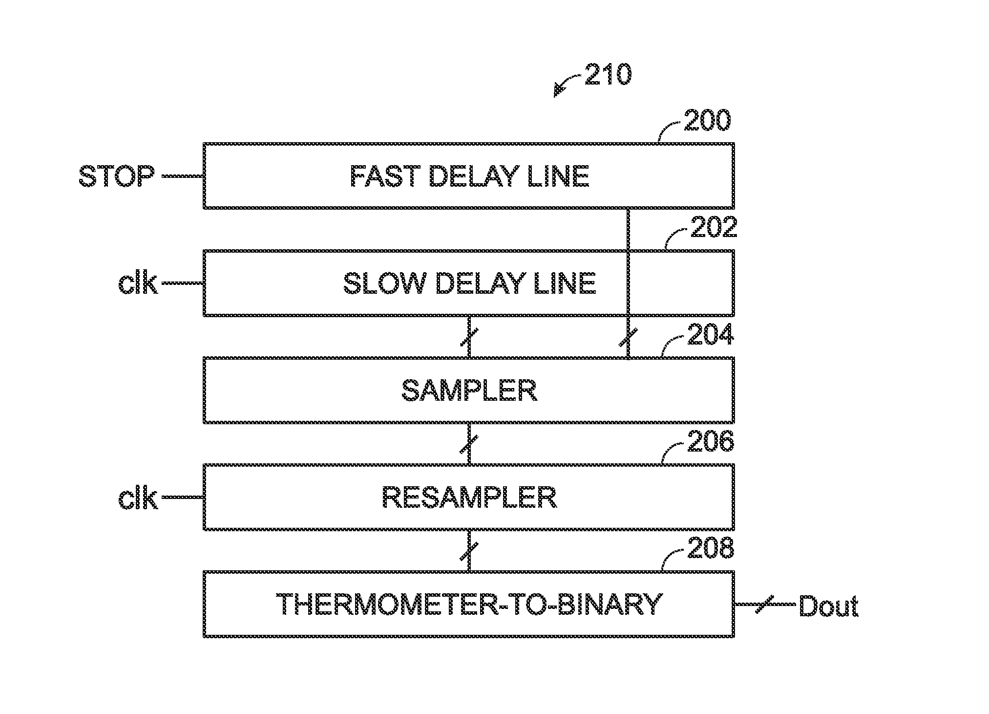
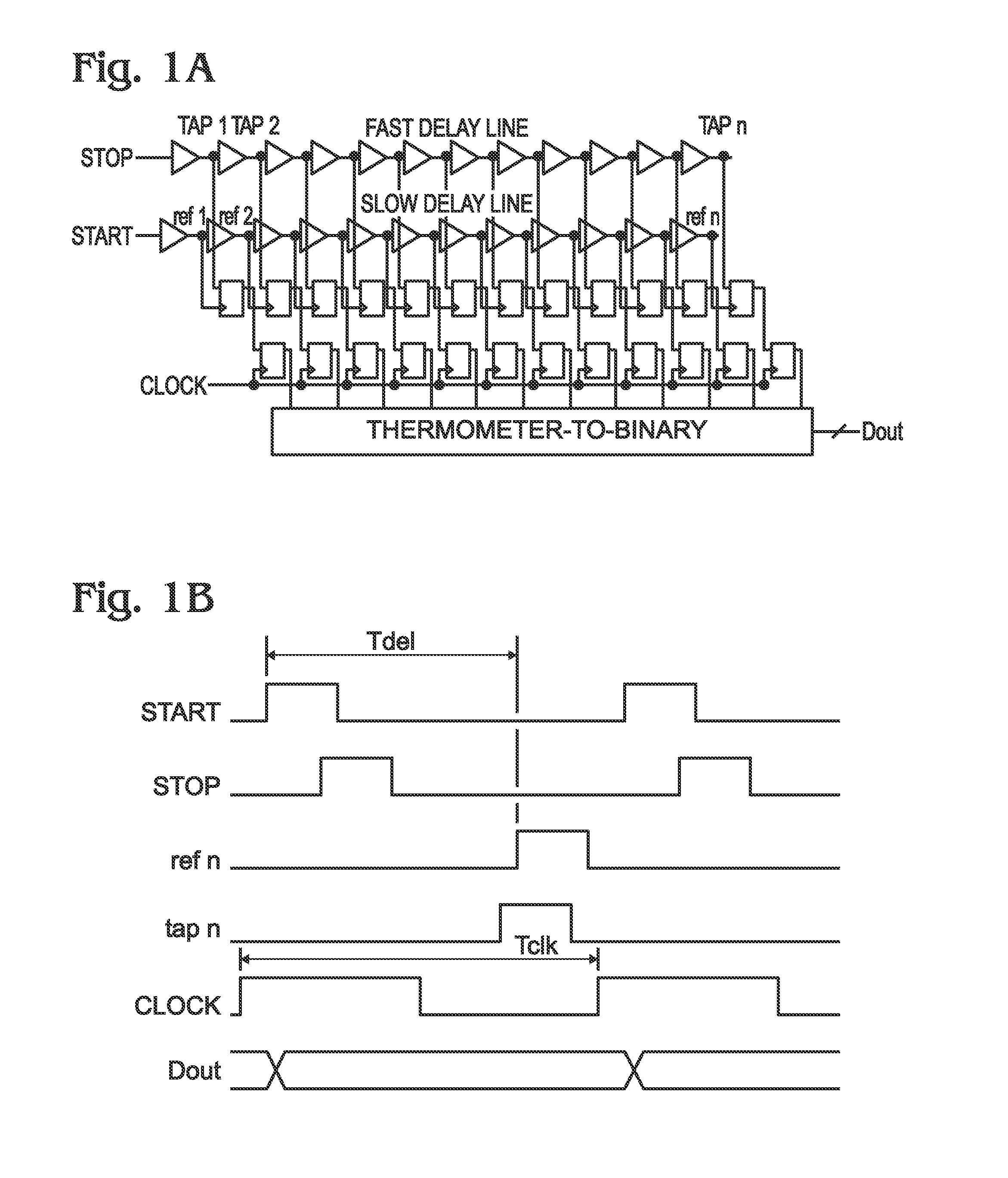
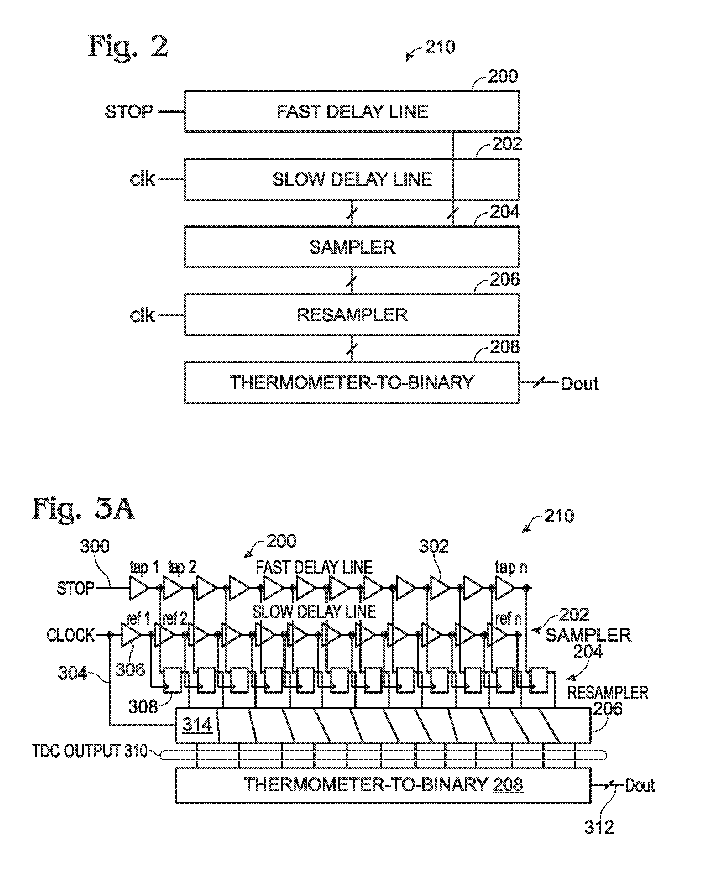
[0024]FIG. 2 is a block diagram of a Traveling Pulse Wave Quantizer (TPWQ). The TPWQ 210, which may also be referred to as a pipelined Vernier delay line time-to-digital converter, comprises a fast delay line 200 to accept a stop pulse and slow delay line 202 to accept a clock (CLK) pulse. As described in greater detail below, measurements from the fast delay line 200 and slow delay line 202 are fed into sampler 204. To this point, the circuitry is similar to the conventional design depicted in FIG. 1A. A resampler 206 accepts the clock signal and information from the sampler 204. Optionally, the results from the resampler 206 are fed to a thermometer-to-binary block 208, which provides a digital output (Dout).

[0025]FIGS. 3A and 3B are, respectively, a schematic block diagram and associated timing diagram, describing the TPWQ block diagram of FIG. 2 is greater detail. The fast delay line 200 has an input on line 300 to accept a first stop signal followed (in time) by a second stop s...


PUM


Abstract

A Traveling Pulse Wave Quantization method is provided for converting a time sensitive signal to a digital value. A first stop signal is delayed by a first time delay, a first plurality of times, to create a delayed first stop signal. A clock signal is delayed by a second time delay, a first plurality of times, to create a delayed clock signal first period. Each second time delay is associated with a corresponding first time delay, and the second time delay is greater than the first time delay. When the delayed first stop signal occurs before the delayed clock signal first period, a count of the delays is stopped and converted into a digital or thermometer value. An accurate resampled value is provided regardless of the duration in delay between the first stop signal and a second stop signal that is accepted after the first stop signal.

Description

BACKGROUND OF THE INVENTION[0001]1. Field of the Invention[0002]This invention generally relates to electronic circuitry and, more particularly, to a Traveling Pulse Wave Quantizer.[0003]2. Description of the Related Art[0004]FIGS. 1A and 1B are, respectively, a schematic diagram of a Vernier delay line (VDL) based time-to-digital converter (TDC), and an associated timing diagram (prior art). A VDL TDC is a popular choice for applications that require fine time resolution. It is based on the use of two parallel tapped delay lines, one fed with reference (start) pulses and the other line with signal (stop) pulses. The fast delay line that is used for the signal pulses is constructed or tuned to be slightly faster than the reference slow delay line. The edge of a start (reference) pulse, occurring before the stop signal pulse edge, is used as a reference, travelling along the slow delay line. The stop signal edge arrives later and propagates along the fast delay line, eventually catch...

Claims


Application Information

Patent Timeline
Patent Type & Authority Applications(United States)
IPC IPC(8): G04F10/00H03M1/12
CPCG04F10/005H03M1/1295H03M1/502H03M1/50H03M1/60H03M1/122
Inventor WALTARI, MIKKO
Owner IQ ANALOG
Why Eureka
Try Eureka