
MIMO wireless communication system

a wireless communication system and wireless communication technology, applied in the field of wireless communication systems, can solve the problems of limiting performance, inability to provide the maximum data throughput of the mimo channel, and still be affected by adjacent cells, so as to reduce interference, reduce interference, and high inter-cell interference.

Inactive Publication Date: 2015-07-30
FUJITSU LTD
View PDF4 Cites 20 Cited by
  • Summary
  • Abstract
  • Description
  • Claims
  • Application Information

AI Technical Summary

Benefits of technology

This patent describes a method for reducing interference in a mobile communication network. The method involves selecting precoders and users jointly in two cells to cancel out interference. This can provide better interference cancellation and higher network throughput. The method also takes advantage of the uplink / downlink channel reciprocity in TDD systems and new transmission modes in LTE to improve the pre-coder selection and user selection criteria. Overall, this patent offers a solution for reducing interference and improving network performance.

Problems solved by technology

However, interference from adjacent cells can still be a problem as explained later.
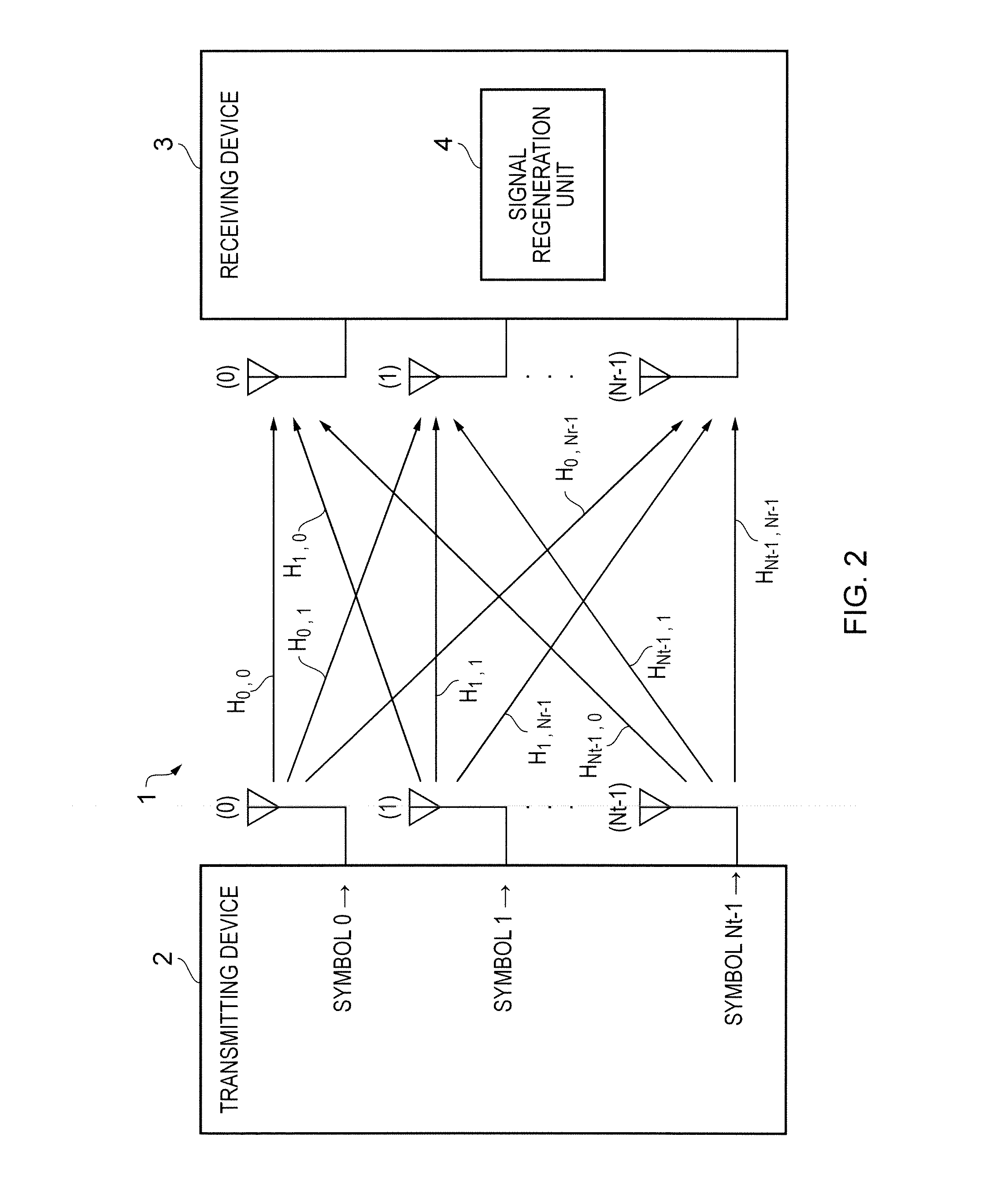
Typically, a base station in a wireless communication system will be equipped with many more antennas in comparison with a mobile handset, owing to differences in power, cost and size limitations.
In such a case, the MIMO channel is incapable of providing the maximum data throughput due to correlation.
In the non-adaptive case, the transmitter does not have any knowledge of the channel properties and this limits performance, as the transmitter cannot take account of changes in conditions (channel profile).
Precoding can be either linear, achieving reasonable results whilst limiting the complexity of processing, or non-linear, achieving near-optimal results but at the cost of greater complexity.
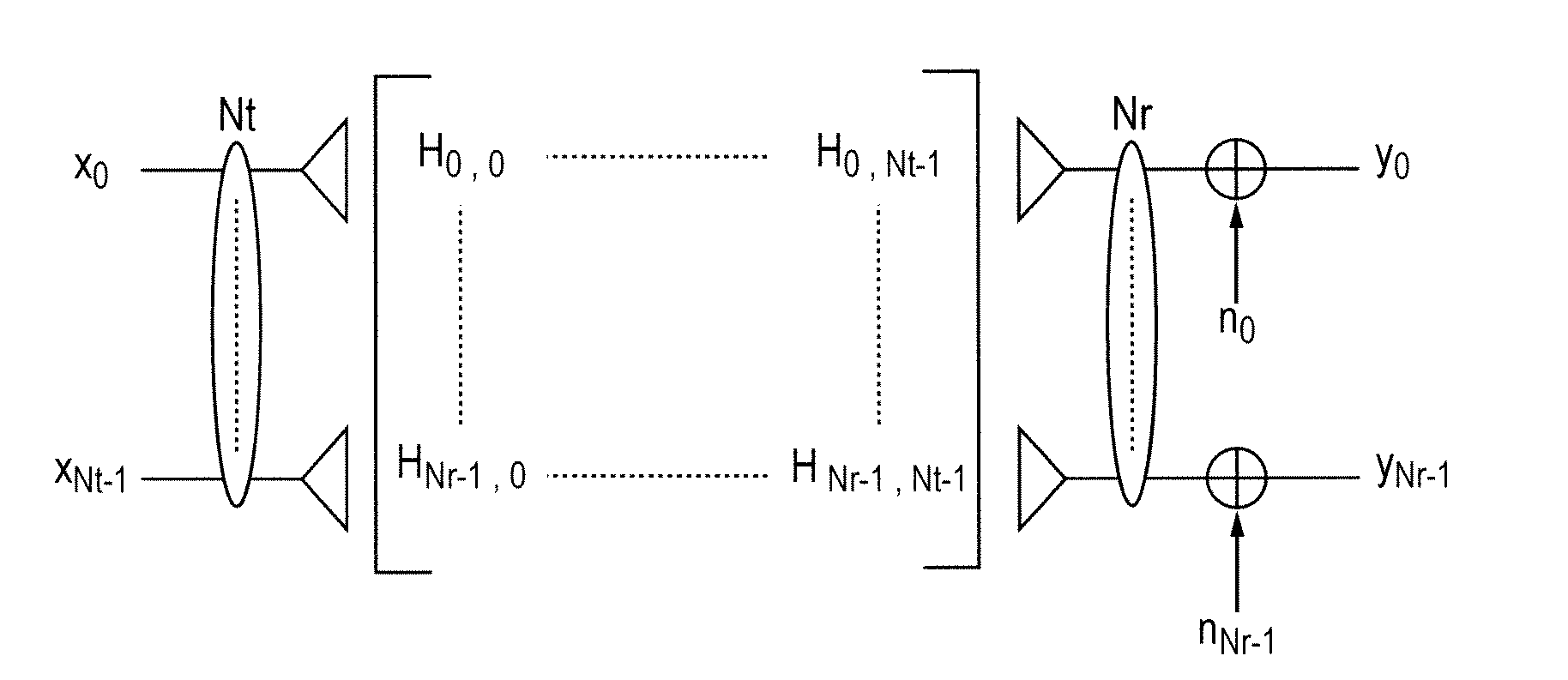
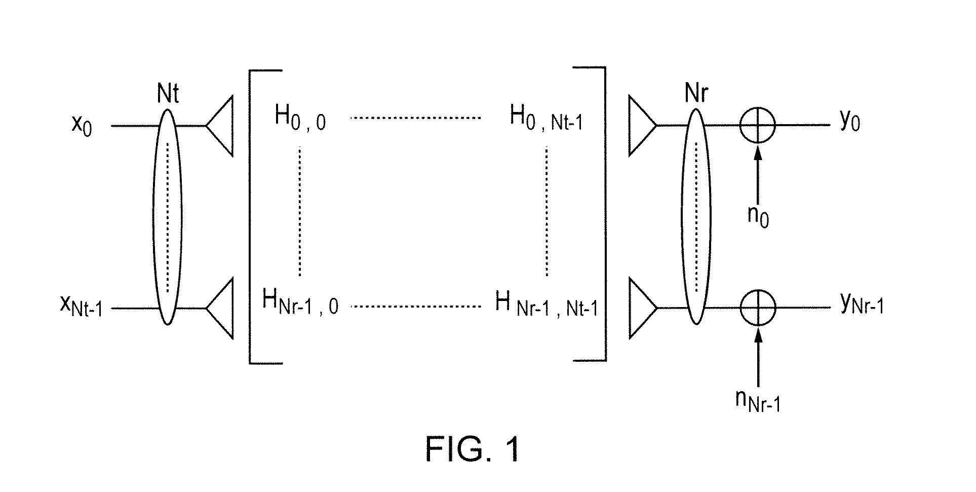
In practice, however, noise n is present and in addition, the channel matrix H cannot be determined with absolute accuracy.
In practice, the adjacent cells overlap to some extent such that transmissions from one base station in one cell can cause interference to users at the edges of adjacent cells.
If the cells have a hexagonal grid arrangement, then one cell may be adjacent to up to six neighboring cells such that transmissions to a particular user may cause interference in more than one other cell.
However, the above multi-user interference effects can become a significant obstacle in achieving the expected capacity enhancements in such systems.
For example, a user near the edge of one cell, communicating with one BS using a particular frequency / time resource, may interfere with a user in an adjacent cell, served by a different BS using the same frequency / time resource.
Consequently, in OFDMA based LTE wireless cellular systems, intercell interference, particularly at the cell edges, can be a significant obstacle in providing a high quality of service.
However when the cells become fully loaded (because LTE supports a frequency reuse of 1, to enable higher throughputs), it becomes very difficult to avoid interference in the above manner.
This problem is aggravated if the signals from supposedly cell centre regions spill over to the cell edges.
A scenario of particular relevance is where the loading of the two cells is such that schedulers cannot allocate resource blocks to UEs which result in sufficiently low interference to allow acceptable performance, implying that the existing time and frequency domain techniques may not be good enough on their own.
In systems known to the art, high levels of inter-cell interference may be experienced by UEs to an extent that existing methods such as FFR and (e)ICIC cannot reduce interference to suitably-low levels.

Method used


Image

  • MIMO wireless communication system
  • MIMO wireless communication system
  • MIMO wireless communication system

Examples


first embodiment

Interference Mitigation Precoder V0 Selection Based on SVD

[0128](a) The default state for the network is as shown in FIG. 1, but with UEB connected to eNBA and eNBB causing strong interference (in other words, prior to handover of UEB). By use of reference signals in TM9 of Rel.10 TD-LTE, eNBA has obtained channel knowledge on HAB, and eNBA stores this knowledge. While UEB is connected to eNBA (before Handover), eNBA can detect the SRS from UEB to estimate the uplink channel. Since in TDD, the uplink and downlink channels can be assumed to be similar, this estimate is valid for the downlink channel HAB.

[0129]The channel HAB is subjected to Singular Value Decomposition (SVD) at eNBA to produce the following matrices of U, D and V, where U denotes the left singular matrix and D the diagonal, singular value matrix. As the channel HAB is asymmetric, the right singular matrix contains signal space matrix Vs and null space matrix V0.

HAB=U·D·V

V=[VsV0]  (3)

[0130]Under normal operation, eNB...

second embodiment

Interference Mitigation Precoder V0 Selection Based on Codebooks

[0140]The embodiment is useful for lower complexity eNBs such as Femto eNBs, which cannot be tasked with carrying out SVD. The Rel.10 TD-LTE system will use TM9 user specific signaling and channel reciprocity to obtain channel knowledge at both eNB and UE ends. However the system reverts back to codebook based transmission mode 4 (TM4) for actual pre-coded data transmissions.

[0141](a) Again the default state for the network is with UEB connected to eNBA and experiencing strong interference from eNBB. The channel knowledge is available at both ends; however, the system has reverted to codebook based PMI mode (TM4) and uses these PMI pre-coders. UEA has indicated the best pre-coder Vs (from the codebook) to eNBA and this is used in pre-coding. Amongst the methods for choosing the pre-coder Vs, the UE can look for maximizing capacity as depicted in eqn (4), iteratively checked for all pre-coders Vn in the codebook. When th...


PUM


Abstract

In a LTE-based wireless communication system, a first user (UEB) in a first cell (Cell A) may experience significant interference from downlink transmissions in a second cell (Cell B). Interference can be reduced by selecting a precoder for downlink transmission to a second user (UEA) in the first cell which will result in reduced interference to the first user (UEB) after the first user (UEB) is handed-over to the second cell. The uplink / downlink channel reciprocity in TDD systems and the new transmission mode TM9 in LTE Release 10 are exploited to obtain channel information and determine precoding. After handover to the second cell, a resource allocation (RBB) to the first user (UEB) is notified to the first cell. In the first cell, the second user (UEA) receives the same resource allocation and a precoder selected to reduce interference to the first user.

Description

CROSS-REFERENCE TO RELATED APPLICATIONS[0001]This application claims the benefit of International Application No. PCT / EP2014 / 050844, filed Jan. 16, 2014, in the PCT Patent Office, and European Application No. 13152050.4, filed Jan. 21, 2013 in the European Intellectual Property Office the disclosures of which is incorporated herein by referenceBACKGROUND[0002]1. Field[0003]The present invention relates to wireless communication systems, and more particularly to wireless communication systems having multiple-input, multiple-output (MIMO) capability, especially but not exclusively Orthogonal Frequency Division Multiple Access (OFDMA) systems including those compliant with the LTE (Long Term Evolution) and LTE-A groups of standards.[0004]2. Description of the Related Art[0005]Wireless communication systems are widely known in which a base station (BS) communicates with multiple subscriber stations (SS or MS, also called users) within range of the BS. The area covered by one BS is calle...

Claims


Application Information

Patent Timeline
IPC IPC(8): H04B7/04H04B15/00H04L5/14
CPCH04B7/0456H04W88/08H04B15/00H04L5/1438H04L5/0023H04L25/03891H04L5/0073
Inventor HUNUKUMBURE, RAJAGURU MUDIYANSELAGE MYTHRI
Owner FUJITSU LTD
Learn More