Conductive tubing

a technology of conductive tubing and conductive wire, which is applied in the field of polymer tubing, can solve the problems of reducing the extrusion rate, and affecting the quality of conductive wire,

Inactive Publication Date: 2015-08-06
TEKNI PLEX
View PDF0 Cites 10 Cited by
  • Summary
  • Abstract
  • Description
  • Claims
  • Application Information

AI Technical Summary

Benefits of technology

[0027]In one embodiment, the electrically conductive material comprises one or more of silver, copper, gold, aluminum, titanium, nickel and stainless steel.
[0028]In one embodiment, th...

Problems solved by technology

Also, because much of the tubing used in medical applications is intended for single (disposable) use, the material and manufacturing costs are of primary concern.
When medical tubing is designed to transmit an electrical current or data signal, in addition to fluid delivery, the product and manufacturing constraints are particularly difficult.
Th...

Method used


Image

  • Conductive tubing
  • Conductive tubing
  • Conductive tubing

Examples


first embodiment

[0063]Referring to FIGS. 3-4, the invention is illustrated. A length of conductive tubing 10 has an elongated cylindrical tubular wall (tube body) 12 disposed along a central longitudinal axis (A) and at least one conductive strip 14 disposed within a tubular passage 20 in the tube body wall 12. In another embodiment (FIGS. 5-6), the at least one conductive strip 24 is disposed within the central axial bore 25 of the tube body 22.

[0064]Tube body 12, 22 is a flexible polymeric tube that is, other than the strip 14, 24, electrically insulating or non-conductive. The tube body 12, 22 has a cross-sectional thickness “t” defined by the body wall between an inner diameter ID (interior surface 12A, 22A) of the tube wall that defines the central lumen or bore 15, 25, and an outer diameter OD (exterior surface 12B, 22B) of the tube body. Each tube body 12, 22 has a first end 17 (e.g., inlet) and an opposing second end 18 (e.g., outlet). In one embodiment, a power source (not shown) is electr...

embodiment 60

[0075]FIG. 8 is a flow chart illustrating one method embodiment 60 of the invention. In a first step 61, a conductive fiber and polymer composite (fiber-polymer matrix) is formed by pultrusion. In a next step 62, the pultruded product is cut into pellets. In next step 63, the pellets are extruded to form a conductive strip in a co-extruded tube wall made of a non-conductive polymeric material.

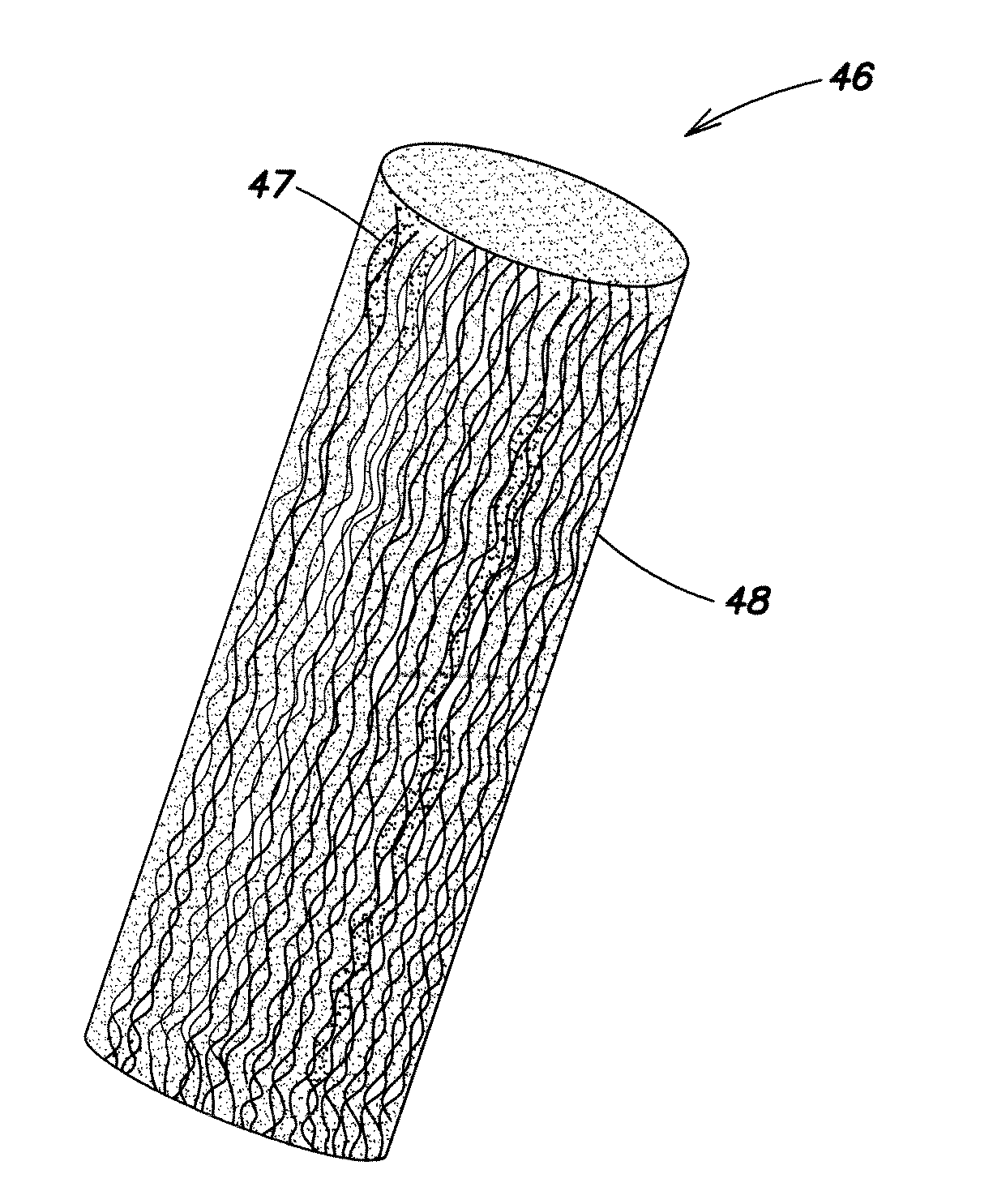
Fiber-Polymer Matrix (Pellet) Manufacture

[0076]FIG. 7A illustrates a magnified view of one end of a pellet 46 of conductive fibers 47 in a plastic matrix 48 according to one embodiment of the invention. The pellet has been cut from a continuous fiber coated bundle manufactured by a pultrusion process, described below. FIG. 7A shows a number of elongated threadlike fibers 47 in the plastic matrix 48 disposed along the elongated pellet axis from one end of the pellet to the other end.

[0077]FIG. 7B is a schematic illustration of one embodiment of a pultrusion process 50 for making such a pellet. A...


PUM

PropertyMeasurementUnit
Lengthaaaaaaaaaa
Lengthaaaaaaaaaa
Lengthaaaaaaaaaa

Abstract

Molded article for medical tubing and the like, and method of manufacture. The molded article is a coextruded tube having a tube wall of a non-conductive thermoplastic polymer and a central tubular bore. The tube further includes a coextruded conductive strip of conductive fibers in a thermoplastic polymer matrix, the conductive strip being disposed within a tubular passage in the tube wall extending the length of the tube, or within the central tubular bore. The strip is made from a pultruded fiber/polymer compound that can be co-extruded in strip form in the tube to provide an electrically conductive path along the tube length. Advantages include ease of manufacture, and one or more of improved handling (during use), reduced profile and reduced material costs.

Description

FIELD OF THE INVENTION[0001]The present invention relates to polymer tubing formed by an extrusion process, the tubing having a fluid delivery channel and a conductive fiber strip for transmission of an electrical current or data signal.BACKGROUND[0002]Plastic tubing is extensively employed in the medical field for various patient treatment and analysis procedures. Depending on the application, various FDA-approved plastics can be used. For example, in the administration of intravenous fluids and in applications where the tubing itself is introduced into the body, the tubing must be inert to the fluid being delivered as well as to the environment in which it is introduced. The tubing should provide a smooth (non-turbulent, non-kinking) fluid flow path and good handling characteristics. Many applications require or prefer clear tubing (clarity). Ideally the overall tubing diameter is minimized, particularly for in vivo applications. Also, because much of the tubing used in medical ap...

Claims


Application Information

Patent Timeline
IPC IPC(8): A61M39/08H01B7/00A61B1/00H01B3/44H01B19/04H01B13/00H01B7/18H01B1/02B29C48/09B29C48/154B29C48/156
CPCA61M39/08B29K2505/10H01B7/0072H01B1/02H01B1/023H01B1/026H01B3/443H01B19/04H01B13/0006A61B1/00018A61M2039/082A61M2207/00B29K2021/006B29L2023/007B29K2505/02B29K2995/0005B29K2505/14B29L2023/005B29C47/0023B29C47/0066B29C47/025B29C47/027B29C47/1045B29K2021/003B29K2023/00B29L2031/7542B29K2023/083B29K2027/06B29C2947/92142B29C2947/9219B29C2947/92238B29C2947/92447B29C2947/92638B29C2947/92685B29C2947/92733B29C2947/92942H01B7/187B29C48/09B29C48/0022B29C48/154B29C48/156B29C48/2886B29C2948/92142B29C2948/9219B29C2948/92238B29C2948/92447B29C2948/92638B29C2948/92685B29C2948/92733B29C2948/92942Y10T29/49117
Inventor BOURGEOIS, PHILIPSHAH, MUNISH
Owner TEKNI PLEX
Why Eureka
Try Eureka