Apparatus for compacting fibrous plant material, especially for compacting stalk material

a technology of fibrous plant material and apparatus, which is applied in the field of apparatus for compacting fibrous plant material, can solve the problem of not being able to achieve complete closure, and achieve the effect of reducing the risk of clogging

Active Publication Date: 2015-08-06
KALVERKAMP KLEMENS DE +1
View PDF6 Cites 4 Cited by
  • Summary
  • Abstract
  • Description
  • Claims
  • Application Information

AI Technical Summary

Benefits of technology

[0010]It is the object of the present invention to create an apparatus for compacting fibrous plant material, in particular stalk material, which allows economically optimized production of pellets, which can realize precompaction that is as great as possible, which ensures as complete utilization of the stalk material as possible, and in which the risk of clogging is reduced.

Problems solved by technology

Approximately closed means in this connection that, on account of manufacturing tolerances of and unavoidable wear phenomena on such an apparatus, complete closing cannot quite be achieved.

Method used


Image

  • Apparatus for compacting fibrous plant material, especially for compacting stalk material
  • Apparatus for compacting fibrous plant material, especially for compacting stalk material
  • Apparatus for compacting fibrous plant material, especially for compacting stalk material

Examples


first embodiment

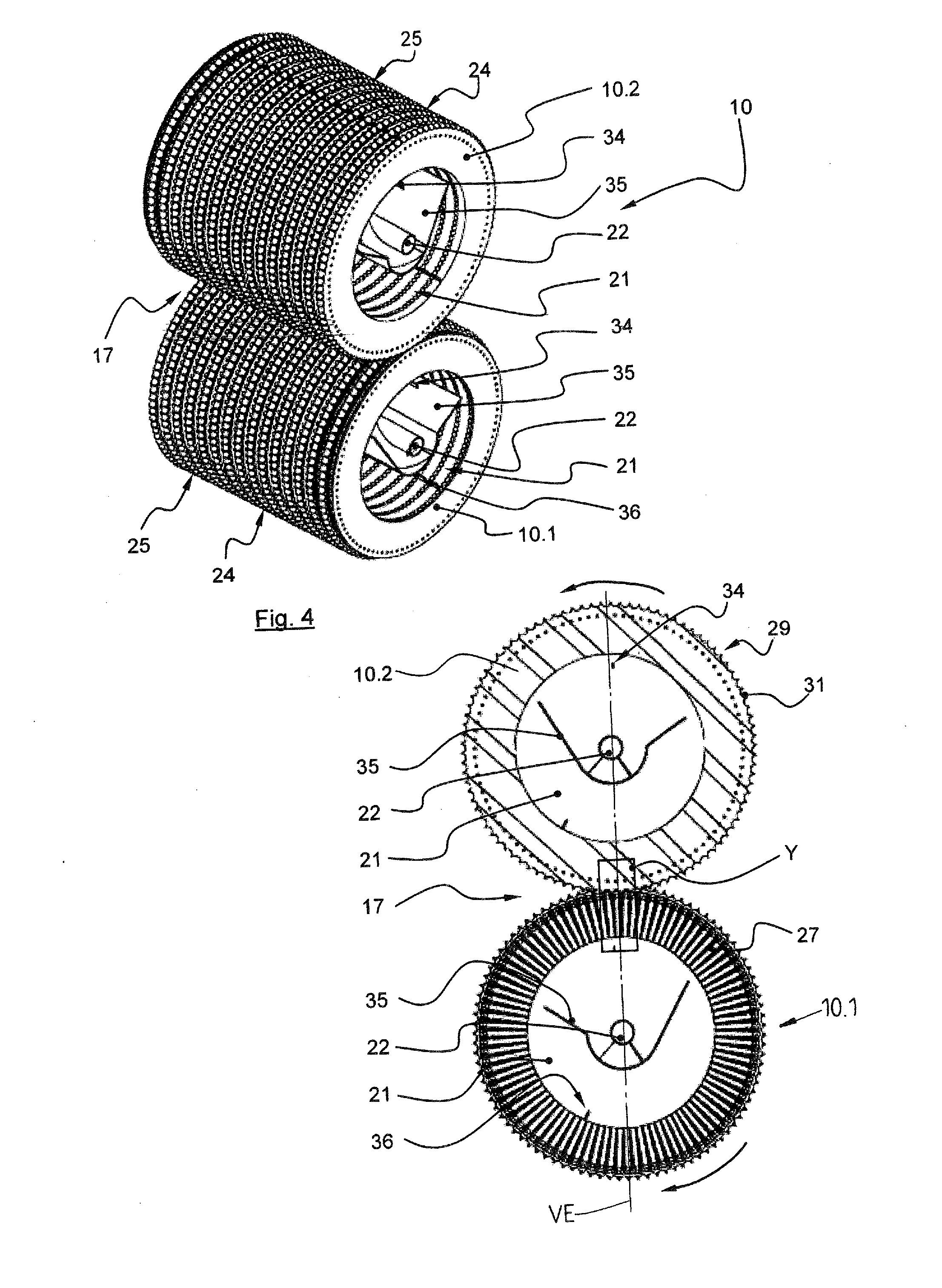
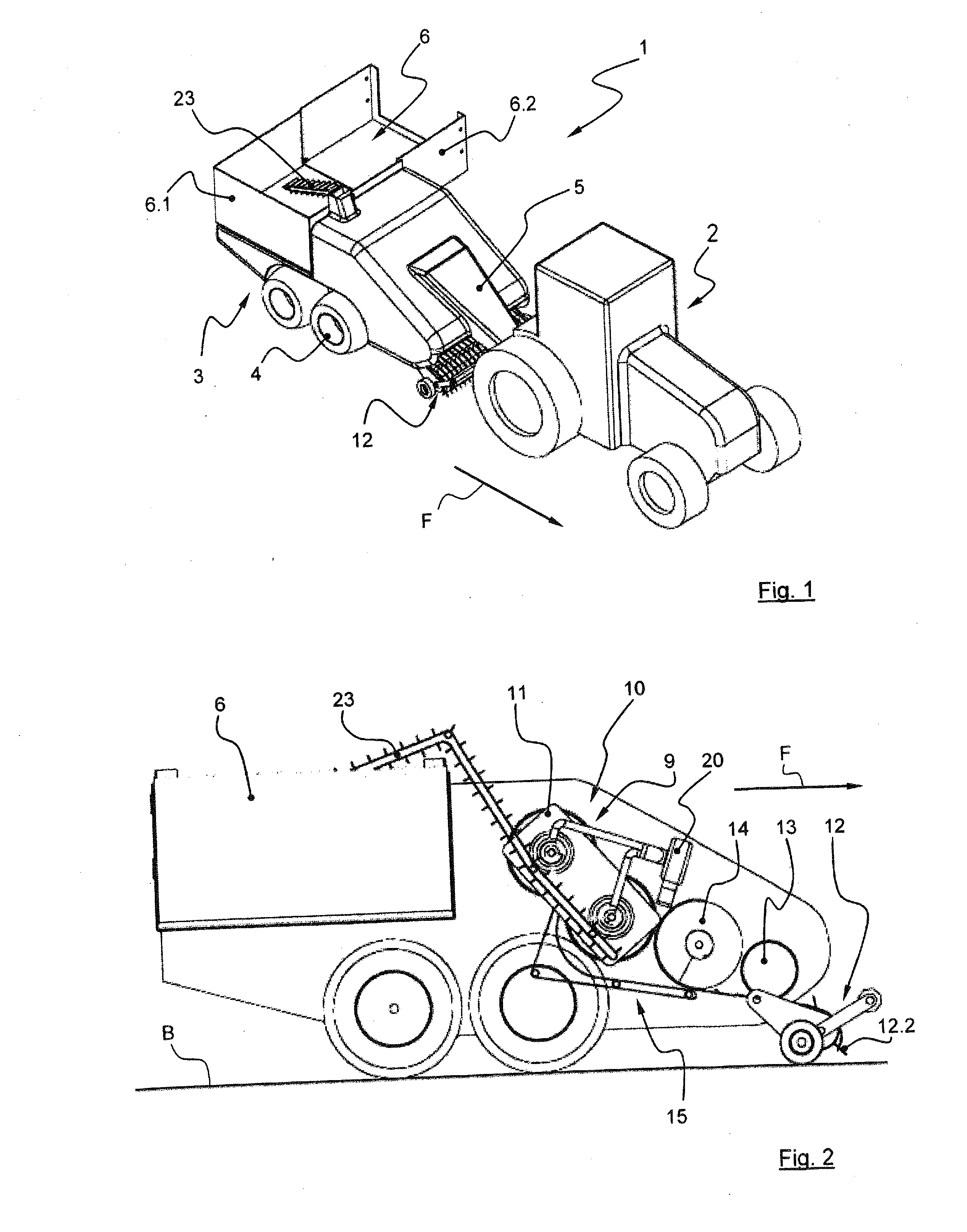
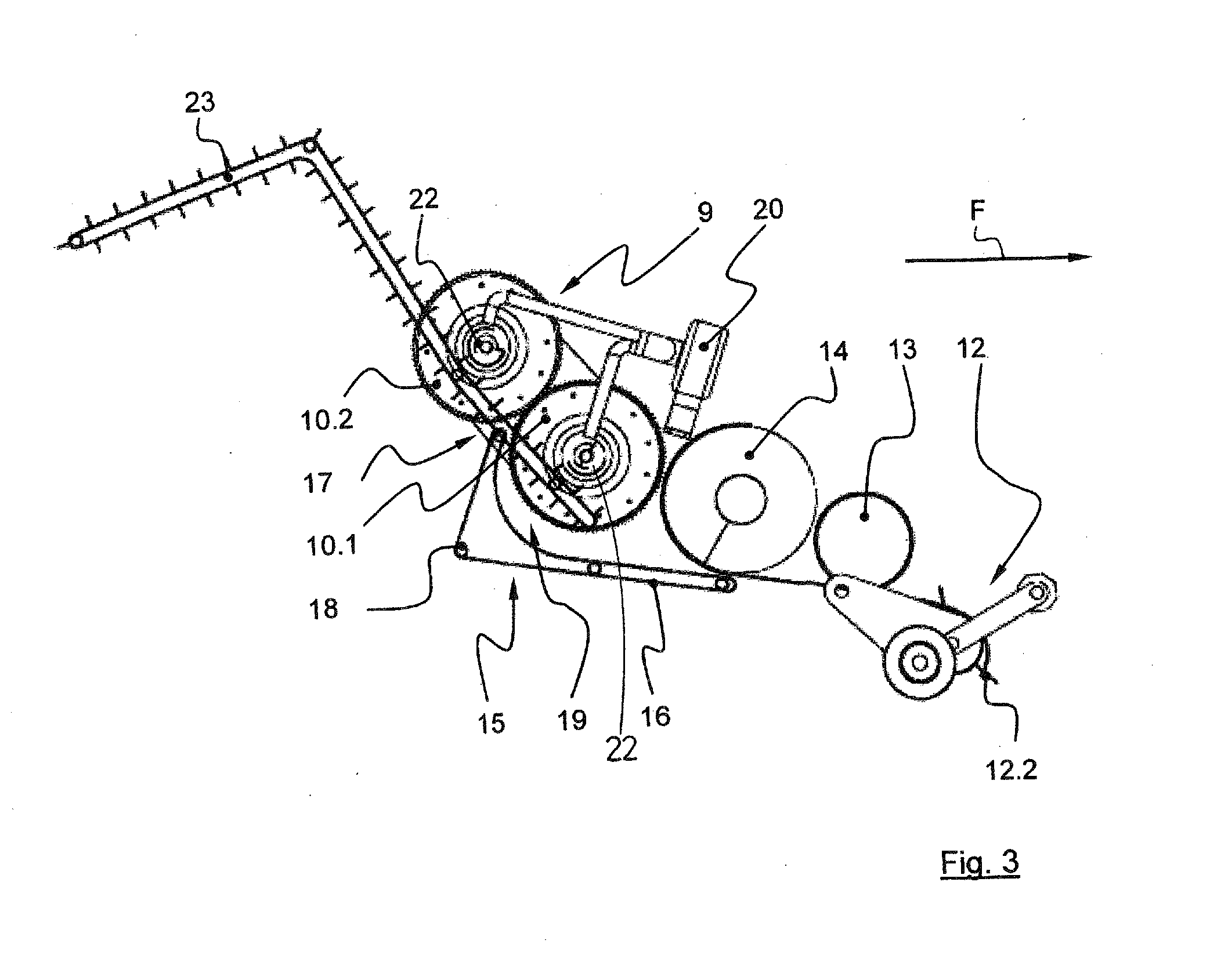
[0063]The partially cutaway side view of the pelletizing machine 1 in FIG. 2 shows the basic arrangement of a first embodiment according to the invention having a press drum pair 9 for forming the pelletizing apparatus 10, wherein the press drum pair 9 is formed by two press drums 10.1, 10.2 that are drivable in opposite directions via a transmission 50 (cf. FIG. 6), said press drums 10.1, 10.2 being mounted in a rotatable manner on a bearing block 11 arranged on the chassis 3. Arranged upstream of the pelletizing apparatus 10 is a pick-up apparatus 12, referred to as a pick-up, a selector 13 arranged downstream of the pick-up apparatus 12 in the direction of travel F and a feed screw 14 arranged downstream of said selector 13 in the direction of travel F.

[0064]The pick-up apparatus 12 can be configured for example as a driven roll 12.1 having tines 12.2, arranged in a distributed manner on the circumference, for picking up the stalk material, for example straw. To this end, the tin...

second embodiment

[0078]In FIG. 11, a pelletizing machine 1 having the feeding apparatus 15 and pelletizing apparatus 10 according to the invention is discernible, wherein, instead of a selector 13, provision is made of a stone crusher 38, consisting of two drums 39 that rotate against one another. The front end, in the conveying direction R, of the conveyor belt 16 is guided up to the lower drum 39. The stone crusher 38 is arranged between the pick-up apparatus 12 and the feeding device 15 and crushes stones or the like which have been picked up by the pick-up apparatus 12.

[0079]FIGS. 12 and 13 show a further embodiment of the pelletizing machine 1 having the feeding device 15 and pelletizing apparatus 10 according to the invention, wherein here the pair of press drums 9 with the press drums 10.1, 10.2, and the feeding device 15 are arranged in a manner rotated substantially through 90° with respect to the first embodiment, such that the rotation axes D of the press drums 10.1, 10.2 and of the rolle...


PUM

PropertyMeasurementUnit
wrap angleaaaaaaaaaa

Abstract

An apparatus for compacting stalk material, having a feeding device for feeding material to be pressed, having at least one pair of press drums which can be driven in opposite directions and which each have circumferential receiving grooves and compression rings in an alternate manner alongside one another in the axial direction, wherein the compression rings of one press drum engage in the receiving grooves of the other press drum, wherein at least one press drum is provided with a cavity and wherein this at least one press drum has a multiplicity of radially extending press channels in a manner distributed over the circumference, said press channels in each case connecting the groove bottom of the receiving grooves to the cavity, provision is made for the compression rings to have a circumferential profile having protrusions formed for example by radially external teeth having tooth tips.

Description

STATEMENT OF RELATED APPLICATIONS[0001]This patent application is the US National Phase of International Application No. PCT / EP2013 / 002638 having an International Filing Date of 3 Sep. 2013, which claims priority on German Patent Application No. 10 2012 017 549.3 having a filing date of 5 Sep. 2012.BACKGROUND OF THE INVENTION[0002]1. Technical Field[0003]The invention relates to an apparatus for compacting fibrous plant material, in particular for compacting stalk material, having a feeding device for feeding the plant material or stalk material to be compacted, having at least one pair of press drums that are settable into opposite rotational movements, wherein one press drum has receiving grooves on its circumference along its axial longitudinal extent and another press drum has compression rings along its axial longitudinal extent, and having an internal cavity in at least one press drum, said internal cavity being connected to the receiving grooves via a multiplicity of radially...

Claims


Application Information

Patent Timeline
Patent Type & Authority Applications(United States)
IPC IPC(8): B30B3/00
CPCB30B11/28B30B3/005B30B15/308B29B9/10
Inventor KALVERKAMP, KLEMENSKALVERKAMP, FELIX
Owner KALVERKAMP KLEMENS DE
Why Eureka
Try Eureka