
Method and Device for Measuring Levels of Cast Iron and Slag in a Blast Furnace

a technology of slag level measurement and blast furnace, which is applied in the direction of furnaces, instruments, manufacturing converters, etc., can solve the problems of crucible being a major obstacle to the development of methods for precise liquid level measurement, and not allowing to provide a reliable indication of the thickness of the slag layer

Active Publication Date: 2015-08-06
CENT DE RECH METALLURGIQUES CENT VOOR RES IN DE METALLURGIE
View PDF7 Cites 4 Cited by
  • Summary
  • Abstract
  • Description
  • Claims
  • Application Information

AI Technical Summary

Benefits of technology

The device described in this patent is easy to install and can be quickly replaced if needed. It is placed on the outside of a blast furnace, which is not very hot, and can be easily replaced if needed. Overall, this device is simple and inexpensive, but still effective at improving the performance of the blast furnace.

Problems solved by technology

However, such a device does not allow to provide a reliable indication on the thickness of the slag layer because of the high temperature of the molten metal (above 1000° C.) which may interfere with the reading.
However, this technology does not allow to measure the surface level of the slag.
The temperature of more than 1000° C. prevailing inside the crucible is thus a major obstacle to the development of methods for the precise measurement of liquid levels.
However, this technology does not allow to measure the level of the cast iron-slag interface, the precise knowledge of which is absolutely crucial in order to separate the cast iron from the slag.
It would not be possible to use this device in a blast furnace given that forming a groove in the wall is precluded at the risk of weakening the shielding of the crucible.
This measurement is somewhat imprecise and does not allow to measure the level of any possible slag.
This method cannot be applied to the thick wall of a blast furnace because the strain then affects all the gauges.

Method used


Image

  • Method and Device for Measuring Levels of Cast Iron and Slag in a Blast Furnace
  • Method and Device for Measuring Levels of Cast Iron and Slag in a Blast Furnace
  • Method and Device for Measuring Levels of Cast Iron and Slag in a Blast Furnace

Examples


Embodiment Construction

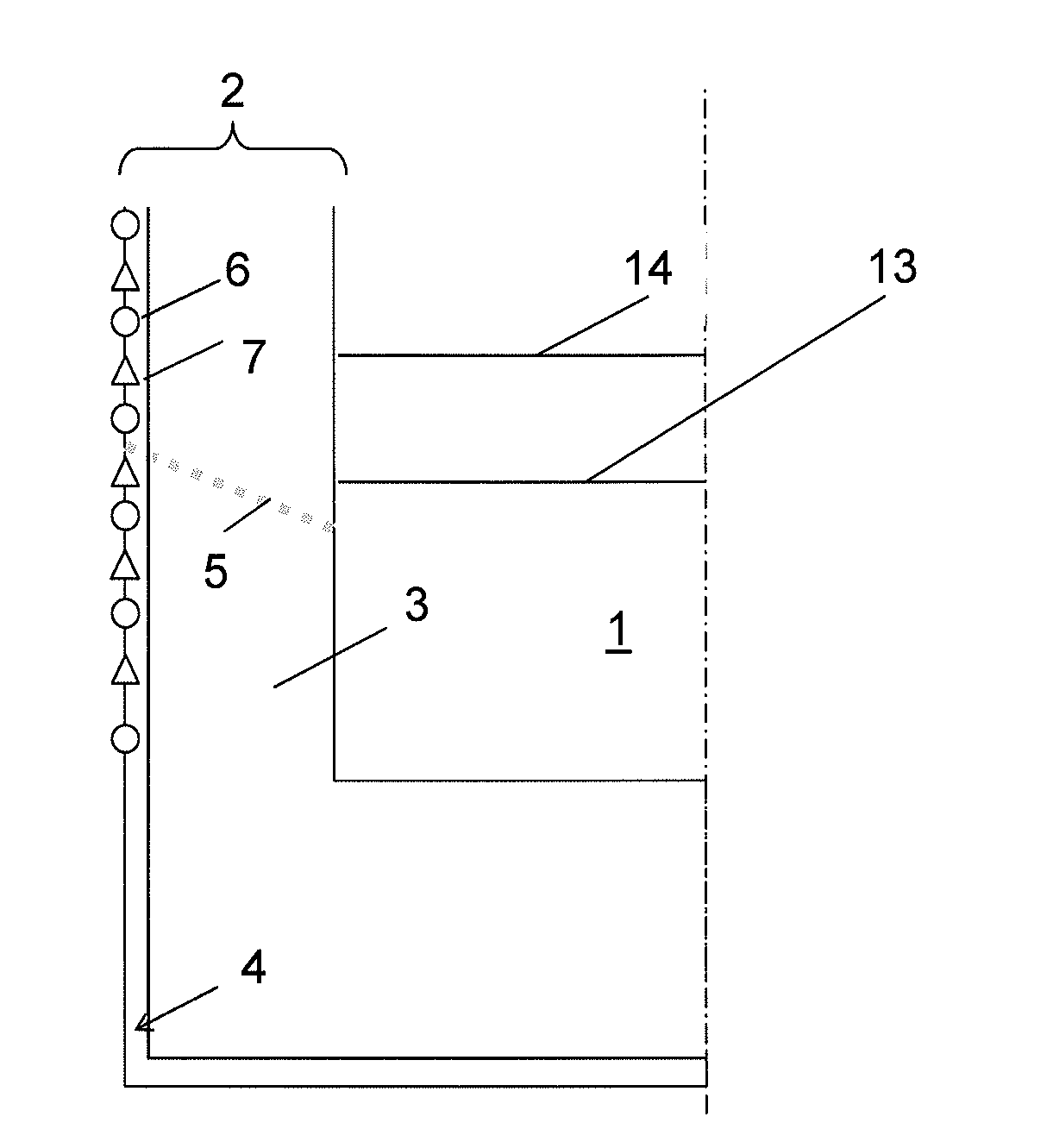
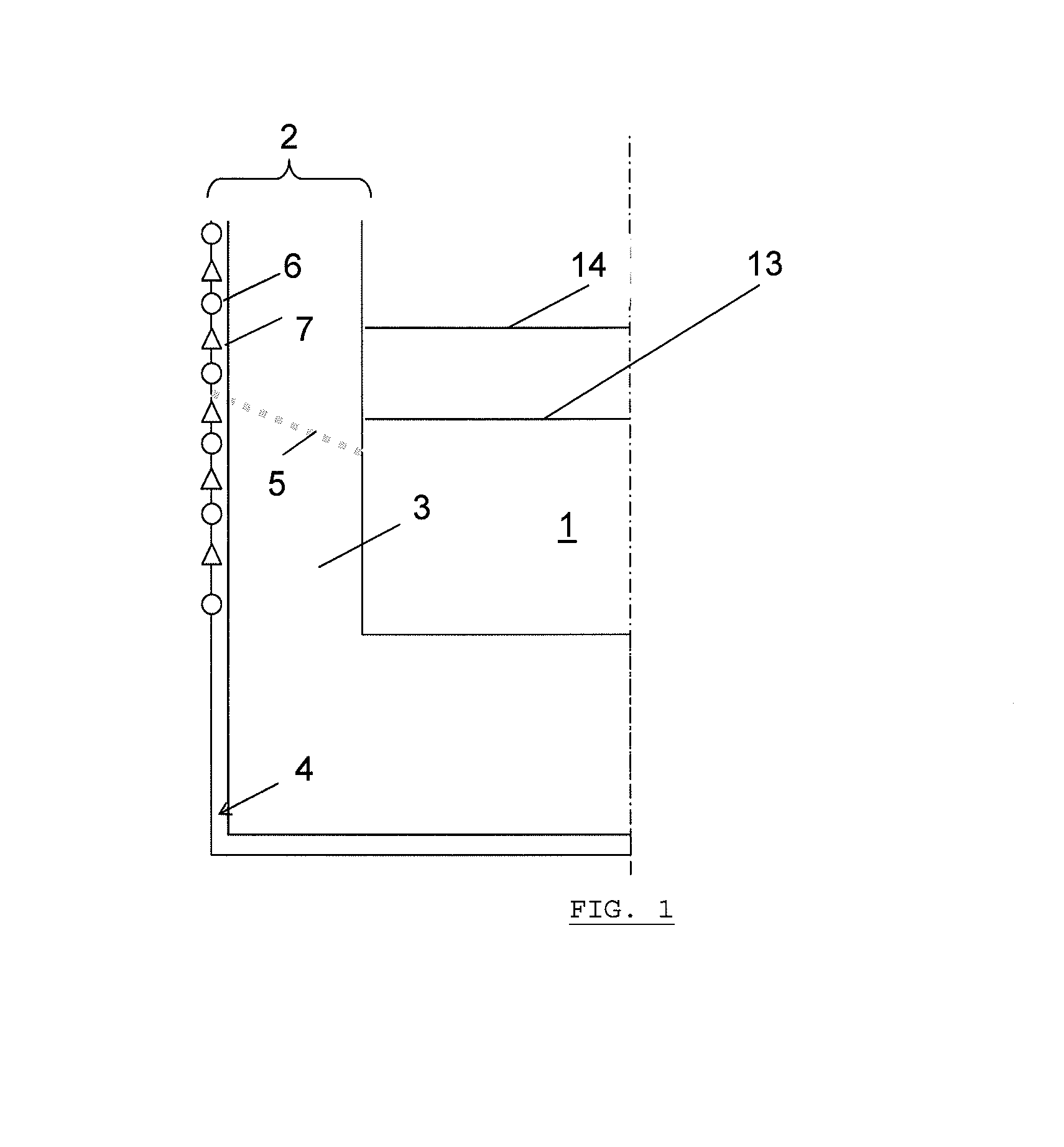
[0049]FIG. 1 is a schematic representation of the vertical cross-section of the wall 2 of the crucible 1 of a blast furnace. The wall is made up of refractory materials 3 and of a steel shielding 4. According to a preferred embodiment of the device of the invention, the steel shielding of the external wall is equipped with strain gauge sensors 6 represented by circles alternating with thermal sensors 7 represented by triangles. FIG. 1 shows a non-limiting example with six strain gages sensors 6 and five thermal sensors 7, attached onto the external surface of the steel shielding 4. The positioning of the tap hole 5 is also indicated.

[0050]At the high temperatures prevailing within the crucible 1, the refractories 3 may soften and / or be subject to erosion and corrosion. Without a cooling system, their operational life would be limited. The cooling is achieved by circulating water through the plates and pipes encased in the walls of the blast furnace. The crucible 1 of a blast furnace...


PUM

PropertyMeasurementUnit
Temperatureaaaaaaaaaa
Thicknessaaaaaaaaaa
Electrical resistanceaaaaaaaaaa

Abstract

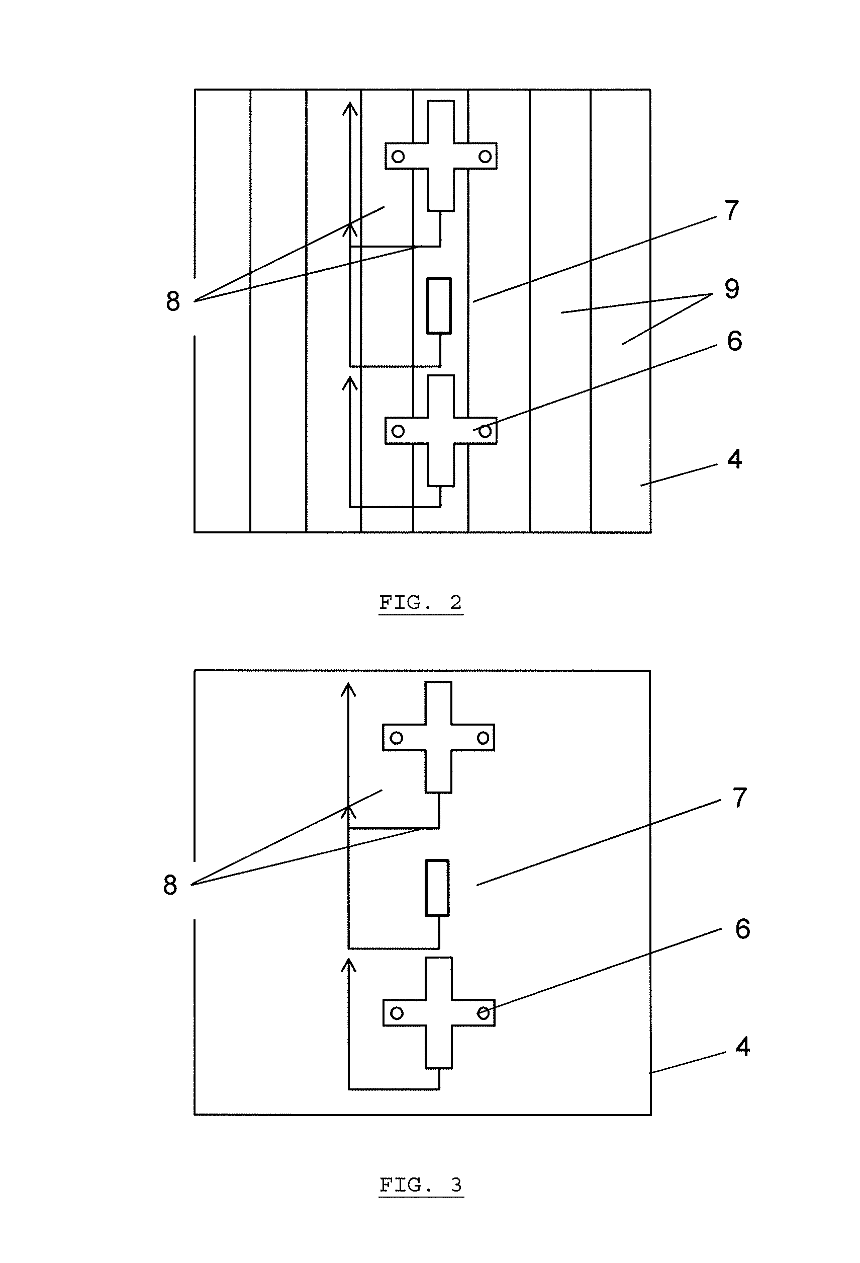
The present invention relates to a method for measuring the liquid-metal surface level (13) and the slag surface level (14) in the crucible (1) of a metallurgical shaft furnace comprising the following steps: measuring, at one or more points on the external wall (2) of the crucible, the following variables: the circumferential strain in said external wall (2) by means of a number of strain-gauge sensors (6) fixed to the armour (4) of the external wall (2) of the crucible; and the temperature of said external wall (2) by means of one or more temperature sensors (7) fixed to the armour (4) of the external wall (2) of the crucible; introducing said variables measured at a number of points on the external wall of the crucible into the general equation governing circumferential strain, the solution of which is analytical, and which contains two unknowns, the liquid metal level and the overall liquid metal / slag level, considering set parameters; and solving said equation and obtaining an analytical solution giving the liquid metal surface level (13) and the slag surface level (14) in the crucible (1).

Description

FIELD OF THE INVENTION[0001]The present invention relates to a method for measuring with precision the level of liquid metal as well as the level of dross or slag floating on the surface thereof inside the crucible of a metallurgical shaft furnace, in particular the level of cast iron and the level of slag in a blast furnace. Particularly, the method consists in using one or more strain gauge sensors mounted on the external wall of the blast furnace.[0002]The invention also relates to a specific strain gauge sensor used in the method.STATE OF THE ART[0003]It is a known fact that a blast furnace is a carbothermic reduction furnace, designed to produce cast iron from iron ore. To achieve this, solid coke and iron ore are charged through the top of the furnace into a section known as the throat. Hot air (1200° C.) blown in at the base of the furnace causes the combustion of the coke. The carbon deriving from the coke is thus oxidised. This carbon monoxide will reduce the iron oxides an...

Claims


Application Information

Patent Timeline
IPC IPC(8): C21B7/24F27D21/00G01F23/24F27B1/28
CPCC21B7/24C21C5/4673G01F23/14G01F23/22G01F23/246F27B1/28F27D21/0014F27D21/0028C21C2005/5288Y02P10/20
Inventor OJEDA ARROYO, CLAUDIODURIEU, FREDERICESSER, ERIC
Owner CENT DE RECH METALLURGIQUES CENT VOOR RES IN DE METALLURGIE
Learn More