Engine lubrication system

a technology of engine lubrication and pump oil, which is applied in the direction of machines/engines, flexible member pumps, and positive displacement liquid engines. it can solve the problems of engine failure, engine failure, and catastrophic consequences for the uav, and improve the metering accuracy of pumped oil. it improves the metering accuracy of pumped oil

Active Publication Date: 2015-08-06
ORBITAL ENGINE CO PTY LTD
View PDF4 Cites 7 Cited by
  • Summary
  • Abstract
  • Description
  • Claims
  • Application Information

AI Technical Summary

Benefits of technology

[0050]According to a sixth aspect of the invention there is provided a method of delivering lubrication oil to an engine comprising pressurising a supply of the lubrication oil to be received by a pump, and operating the pump to deliver lubrication oil to the engine, wherein the pressurisation of the lubrication oil establishes a positive pressure at the pump inlet to assist delivery of lubrication oil having entrained vapour cavities, wherein the pressurisation of the lubrication oil improves the metering accuracy of the pumped oil and wherein operation of the pump is selectively variable according to vapour cavity entrainment within the lubrication...

Problems solved by technology

It has been found that in such an engine lubrication system, the pump may not necessarily supply oil in a reliable manner to the engine in certain circumstances.
This can lead to engine failure and may have catastrophic consequences for the UAV.
In particular, it has been found that in certain circumstances vapour cavities form in the oil.
The presence of vapour cavities in the oil can detrimentally affect operation ...

Method used


Image

  • Engine lubrication system
  • Engine lubrication system
  • Engine lubrication system

Examples


first embodiment

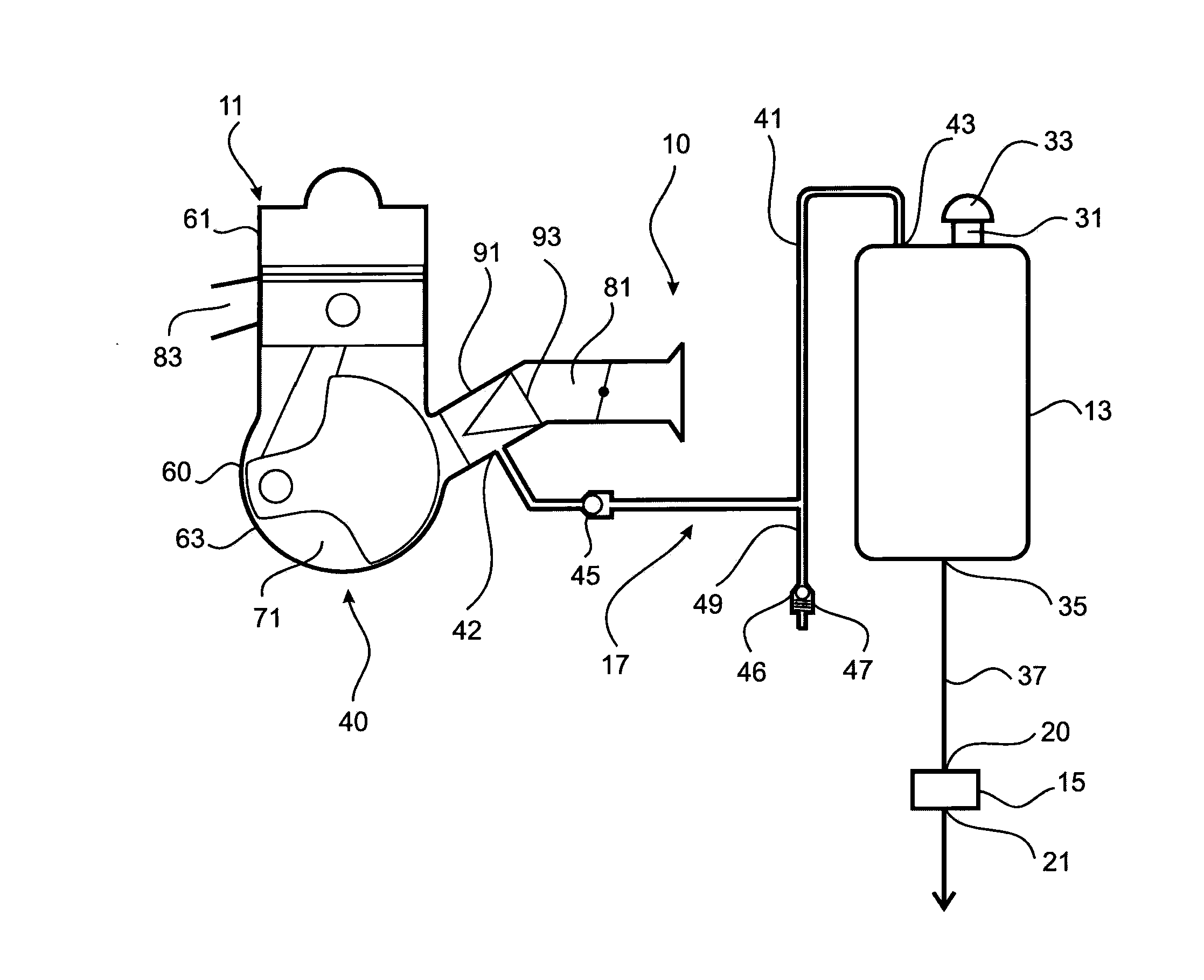
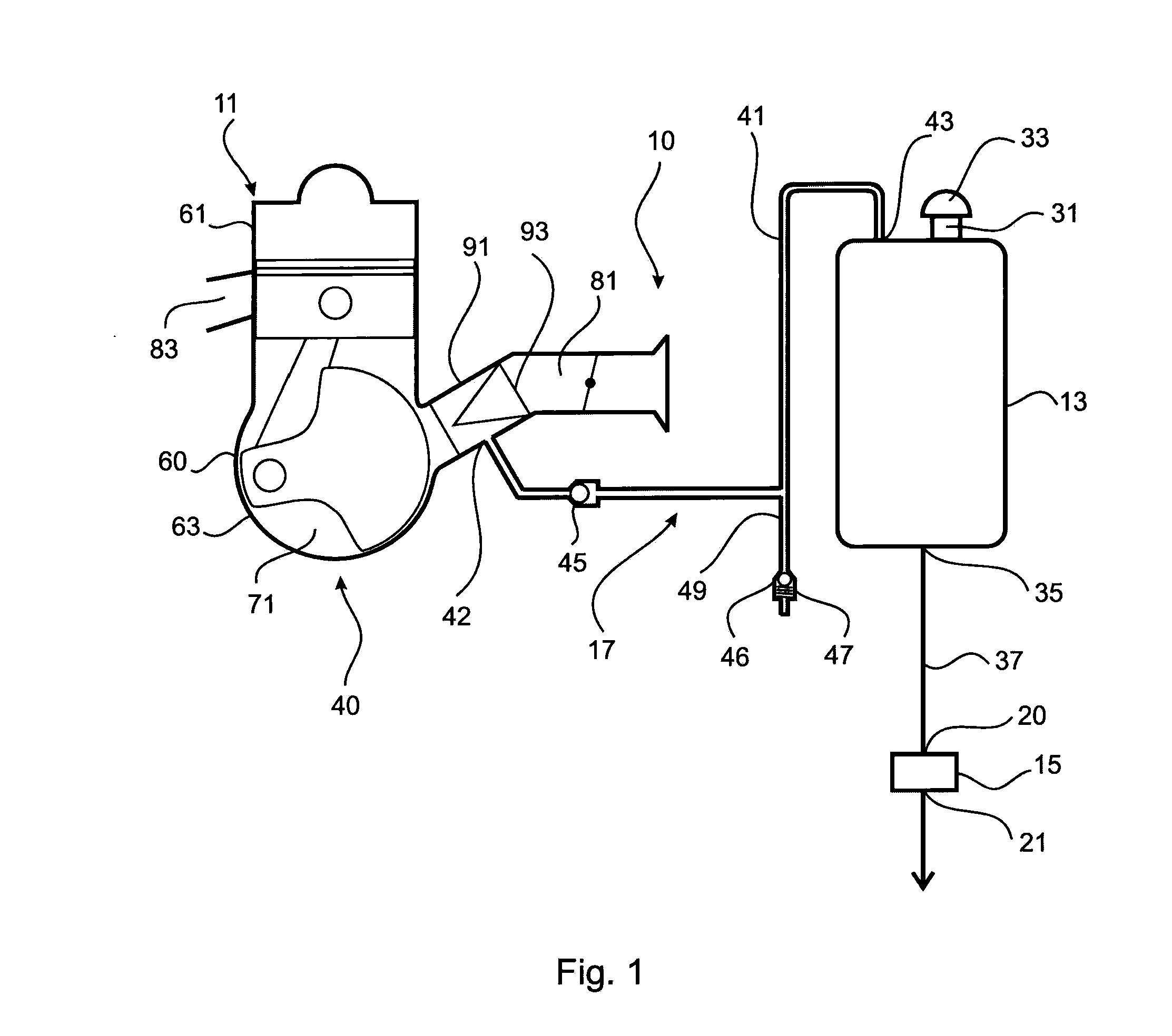
[0101]Referring now to FIGS. 1 to 6, there is shown the engine lubrication system 10. The solenoid actuated positive displacement pump 15 is shown in FIG. 3.

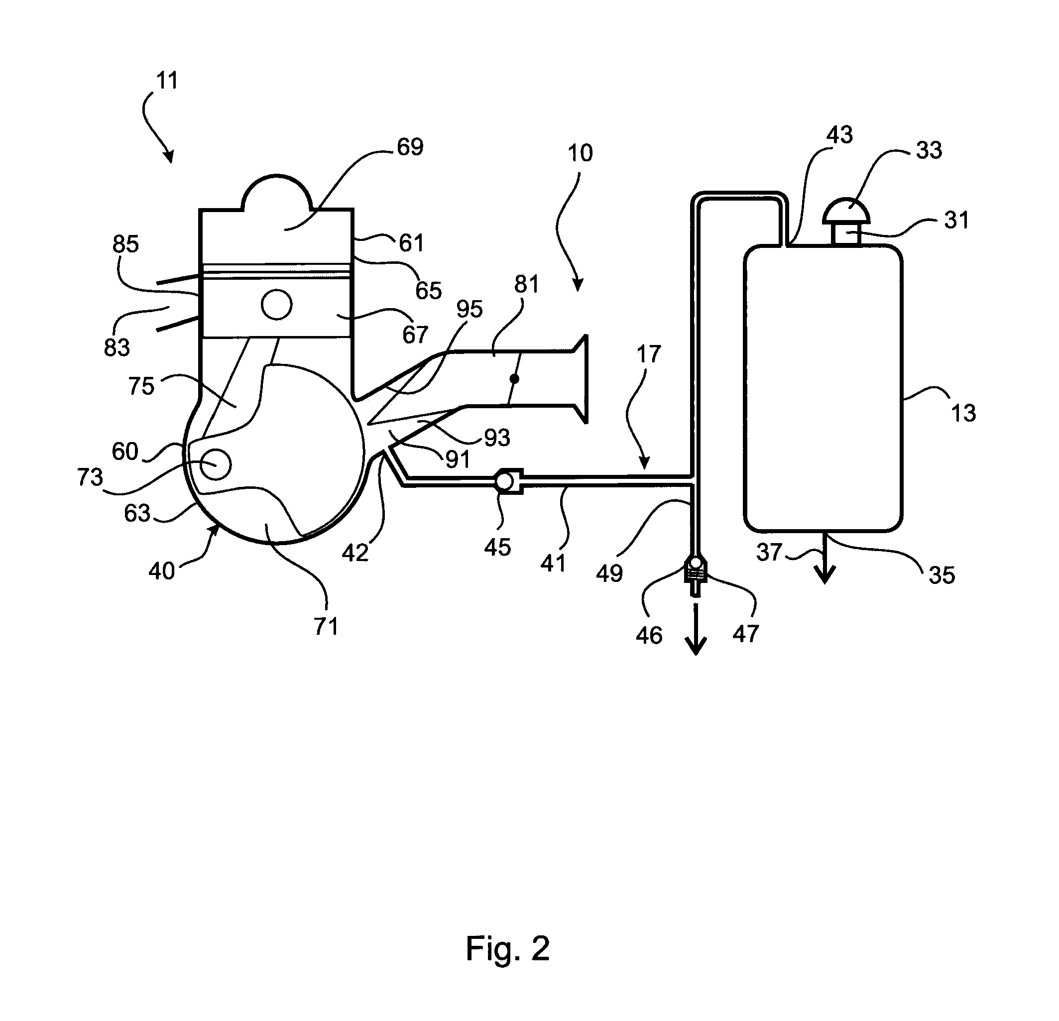
[0102]In this first embodiment, the engine lubrication system 10 utilises crankcase pressure of the engine 11 as the fluid pressure source 40. In particular, the engine 11 is a two-stroke crankcase compression engine comprising an engine body 60 having a cylinder head 61 and an engine block 63, as best seen in FIG. 2. The cylinder head 61 defines a cylinder 65 in which there is a piston 67 which cooperates with the cylinder to define a combustion chamber 69. The engine block 63 defines a crankcase 71 which accommodates a crankshaft 73 which is connected to the piston 67 by connecting rod 75 in known manner.

[0103]The engine 11 has an air intake 81 through which intake air is delivered to the crankcase 71 in known manner. The engine 11 also has an exhaust outlet 83 communicating with the cylinder 65 via an exhaust port 85, again i...

second embodiment

[0111]Referring now to FIG. 7, there is shown the engine lubrication system 10.

[0112]As is the case with the first embodiment, this second embodiment utilises crankcase compression of the engine 11 as the fluid pressure source 40. However, in this second embodiment, the inlet 42 of the fluid pressure supply line 41 is tapped into the engine block 63 at tapping point 121 to communicate directly with the crankcase 71. The tapping point 121 is preferably remote from the point at which lubrication oil is introduced into the crankcase 71. Indeed, it is desirable that the tapping point 121 be on the opposed side of the crankcase 71 to the point at which lubrication oil is introduced into the crankcase. The solenoid actuated positive displacement pump 15 used in this second embodiment is similar to that used in the first embodiment as shown in FIG. 3.

[0113]The engine lubrication system 10 need not necessarily use crankcase pressure of the engine 11 as the fluid pressure source 40. Embodime...


PUM


Abstract

A system and method for delivering lubrication oil to an internal combustion engine. The engine lubrication system (10) comprises a lubrication oil reservoir (13), a pump (15) to deliver lubrication oil to the engine from the reservoir (13), and a pressurisation system (17) for pressurising oil received by the pump from the reservoir for delivery to the engine. The pressurisation establishes a positive pressure at the pump inlet to assist delivery of oil having entrained vapour cavities to the engine for lubrication thereof. The pump (15) comprises a solenoid actuated positive displacement pump, whereby operation of the pump may be selectively controlled by the manner in which the solenoid is operated. The engine lubrication system (10) further comprises a pressure release system (46) comprising pressure relief valve (47) for relieving excess fluid pressure within the oil reservoir (13).

Description

TECHNICAL FIELD[0001]This application claims the benefit and priority of Australian Patent Application 2014900335, filed Feb. 5, 2014. The entire disclosure of the above application is incorporated herein by reference.[0002]The present invention relates to engine lubrication. More particularly, the invention is concerned with a system and method for delivering lubrication oil to an internal combustion engine.[0003]The present invention has been devised particularly, although not necessarily solely, for delivering lubrication oil to a two-stroke internal combustion engine. However, it should be understood that the invention may have application to other internal combustion engines, including in particular four-stroke engines and rotary (Wankel) engines.[0004]Furthermore, the invention has been devised particularly, although not necessarily solely, for use with an engine of an unmanned aerial vehicle (UAV).BACKGROUND[0005]The following discussion of the background art is intended to f...

Claims


Application Information

Patent Timeline
IPC IPC(8): F01M1/02F04B17/04F01M11/00F02B75/02F01M1/18
CPCF01M1/02F02B75/02F01M1/18F01M2001/0223F04B17/04F02B2075/025F01M11/0004
Inventor CATHCART, GEOFFREY PAULRAILTON, DONALD ANDREW
Owner ORBITAL ENGINE CO PTY LTD
Why Eureka
Try Eureka