
Device for producing three-dimensional models with special building platforms and drive systems

a technology of drive system and three-dimensional model, which is applied in the direction of auxillary shaping apparatus, butter production, cheese production, etc., can solve the problems of friction between the conveyor belt and the supporting surface, the construction of components is limited in size and productivity, and the effect of stick/slip

Active Publication Date: 2015-08-13
VOXELJET AG
View PDF3 Cites 80 Cited by
  • Summary
  • Abstract
  • Description
  • Claims
  • Application Information

AI Technical Summary

Benefits of technology

The system described in this patent has the advantage of being easy to expand and scale up by adjusting the grates or adding multiple systems. The components are produced on a single rotating platform, which keeps them in the same position and ensures consistent production. The method can be carried out in batches or continuously, with a continuous unpacking operation combined with other device parts and method steps for efficient production.

Problems solved by technology

As a result, the construction of components is limited with respect to size and productivity.
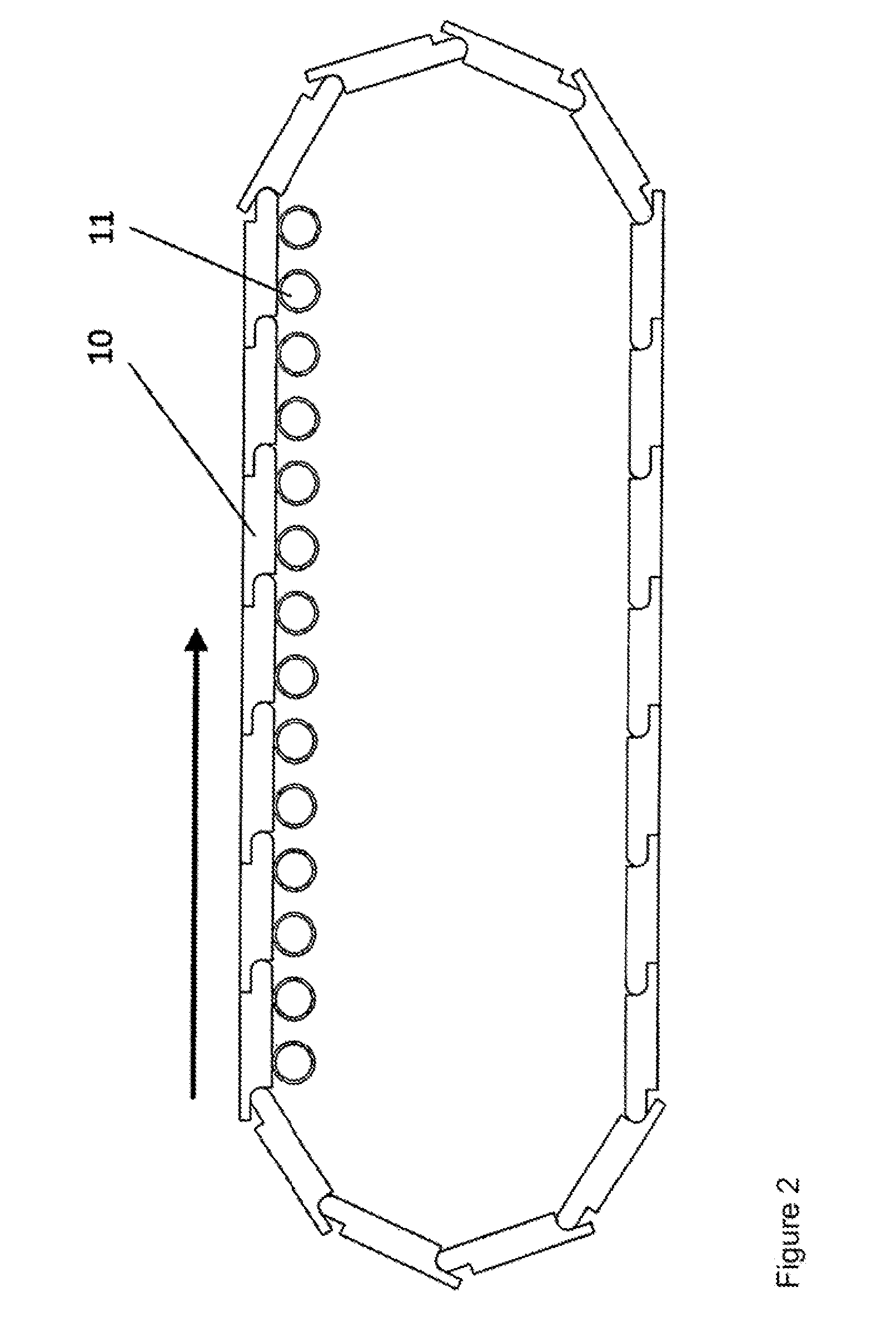
Above a certain width of the conveyor belt or above a certain mass of the particulate material feedstock, the frictional engagement between the conveyor belt and the supporting surface is so great that stick / slip effects may occur, or the drive may fail completely.
If a link conveyor is driven in this manner, an uneven feed results.
At the same time, the bearing of the individual links may prove to be sensitive to contaminants.
If the links do not ideally abut each other, build material may enter the space between two plates via the joints and impair the operation of the flexible connection.
In addition, particulate material may be lost uncontrollably via the joint, which may result in defects in the particulate material feedstock and thus in the components.
This is technologically complex, since the plates must, among other things, be clean for reuse.
The vibration-free and dense placement of a new plate has also proven to be difficult.
The known feeding means for use in a continuous process for building bulky and complex models (components) in layers are thus subject to a large number of problems.
Up to now, no devices and methods are known which are suitable for producing large and heavy models and which avoid the disadvantages described above.

Method used


Image

  • Device for producing three-dimensional models with special building platforms and drive systems
  • Device for producing three-dimensional models with special building platforms and drive systems
  • Device for producing three-dimensional models with special building platforms and drive systems

Examples


Embodiment Construction

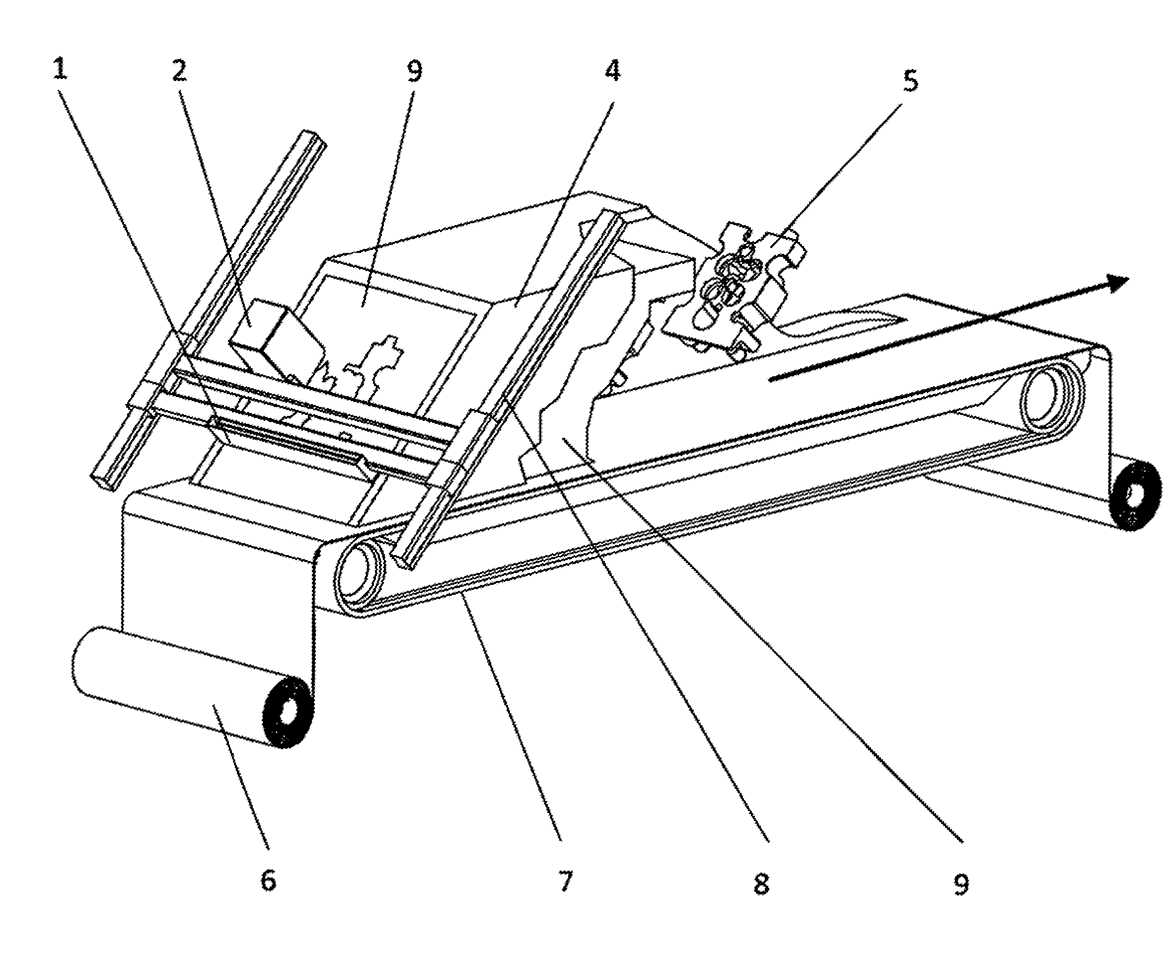
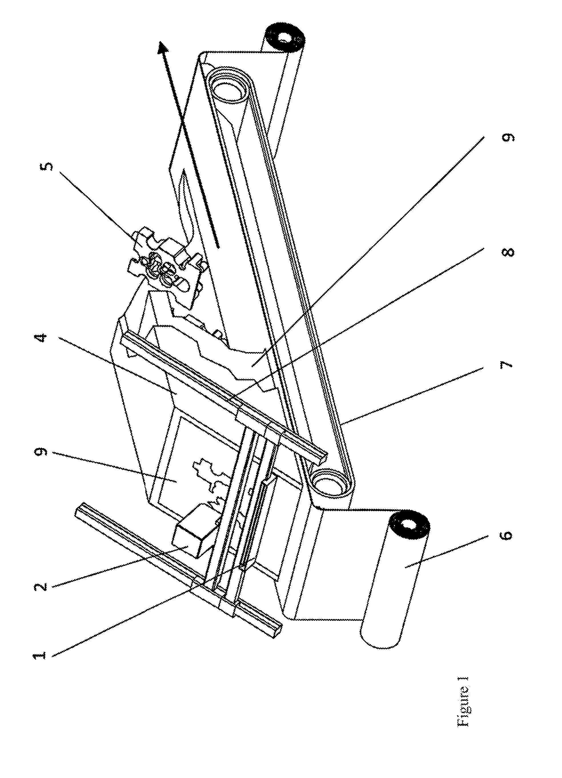
[0018]The invention relates to a device for producing three-dimensional models, preferably in a continuous process, comprising a build surface which has a first end in the direction of movement and a second end in the direction of movement, at least one dosing device and at least one solidification unit, characterized in that the build surface is designed to transport heavy components, and the components are transportable over the build surface essentially without distortion. In preferred embodiments which provide a rotational operation, the first end is understood to be the start of the process, and the second end is understood to be the end of the process, or preferably the unpacking position or the unpacking operation.

[0019]The inventors have advantageously succeeded in providing drives which are suitable for producing bulky and heavy components, in particular in continuous processes, for building models in layers using inclined printing, and which facilitate precise production w...


PUM

PropertyMeasurementUnit
angleaaaaaaaaaa
angleaaaaaaaaaa
weightaaaaaaaaaa

Abstract

The invention relates to a device for producing three-dimensional models in a continuous process, comprising a build surface which has a first end in the direction of movement and a second end in the direction of movement, at least one dosing device and at least one solidification unit, characterized in that the build surface is designed to transport heavy components, and the components are transportable over the build surface essentially without distortion, and also comprising a method therefor.

Description

BACKGROUND OF THE INVENTION[0001]The present invention relates to a system for the continuous production of three-dimensional models on a horizontal transport device, using a layering technique.PRIOR ART[0002]In layering methods used today for producing three-dimensional objects based on computer data, methods are used in which a platform (building platform), which is movable at least in the vertical direction and which, if necessary, is surrounded by a container and thus forms a job box, is placed in an uppermost position at the beginning of the process. A build material, for example a substance in the form of particulate material in the case of 3D printing or laser sintering, is then applied in a thin layer over the entire area of this platform. In another step, the material is selectively bound with the aid of a physical or chemical solidification mechanism according to the desired component shape. This binding step may take place, for example, using adhesives, which may be print...

Claims


Application Information

Patent Timeline
Patent Type & Authority Applications(United States)
IPC IPC(8): B29C67/00
CPCB29C67/0092B29C67/0077B29C67/0074B33Y30/00B29K2103/00B33Y10/00B29K2105/251B29C64/153B29C64/141B29C64/176Y02P10/25B29C64/245B22F12/33B22F12/50B22F12/226B22F10/28B22F12/37B22F10/10B22F10/85B29C64/40
Inventor EDERER, INGOHARTMANN, ANDREAS DOMINIK
Owner VOXELJET AG
Learn More