Wind turbine blade

Inactive Publication Date: 2015-08-20
SIEMENS AG
View PDF2 Cites 14 Cited by
  • Summary
  • Abstract
  • Description
  • Claims
  • Application Information

AI Technical Summary

Benefits of technology

[0016]In order to further reduce the emission of aerodynamic noise it may be envisaged that a serration has a rounded shape at its tip and/or its notch. As sharp edges are avoided a smooth airflow is achieved which prevents the generat

Problems solved by technology

Wind turbine blades generate aerodynamic noise when the wind turbine operates and the rotor is in rotational movement.
It was found out that the main source of aerodynamic noise originates at the trailing

Method used


Image

  • Wind turbine blade
  • Wind turbine blade

Examples


Embodiment Construction

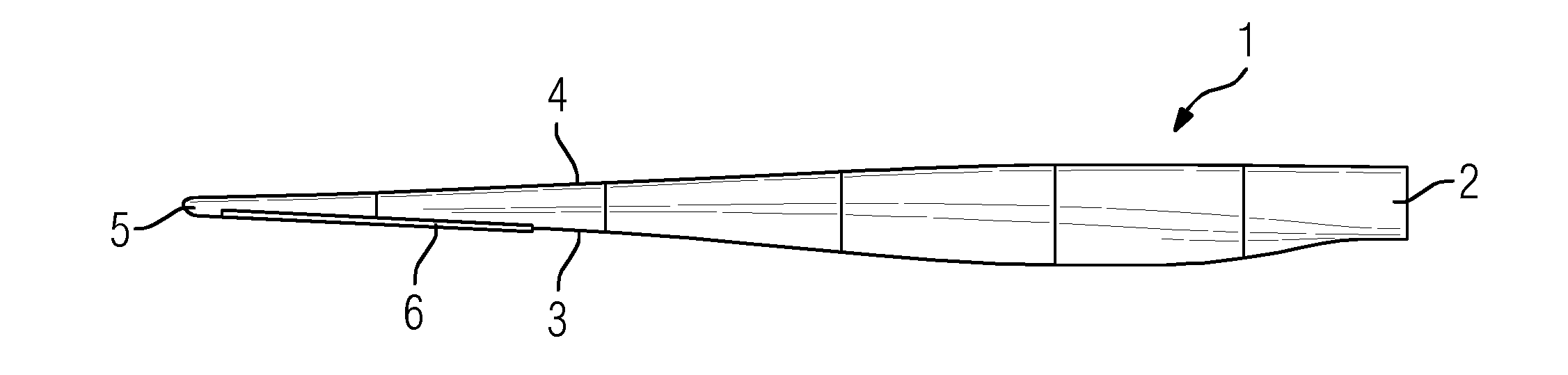
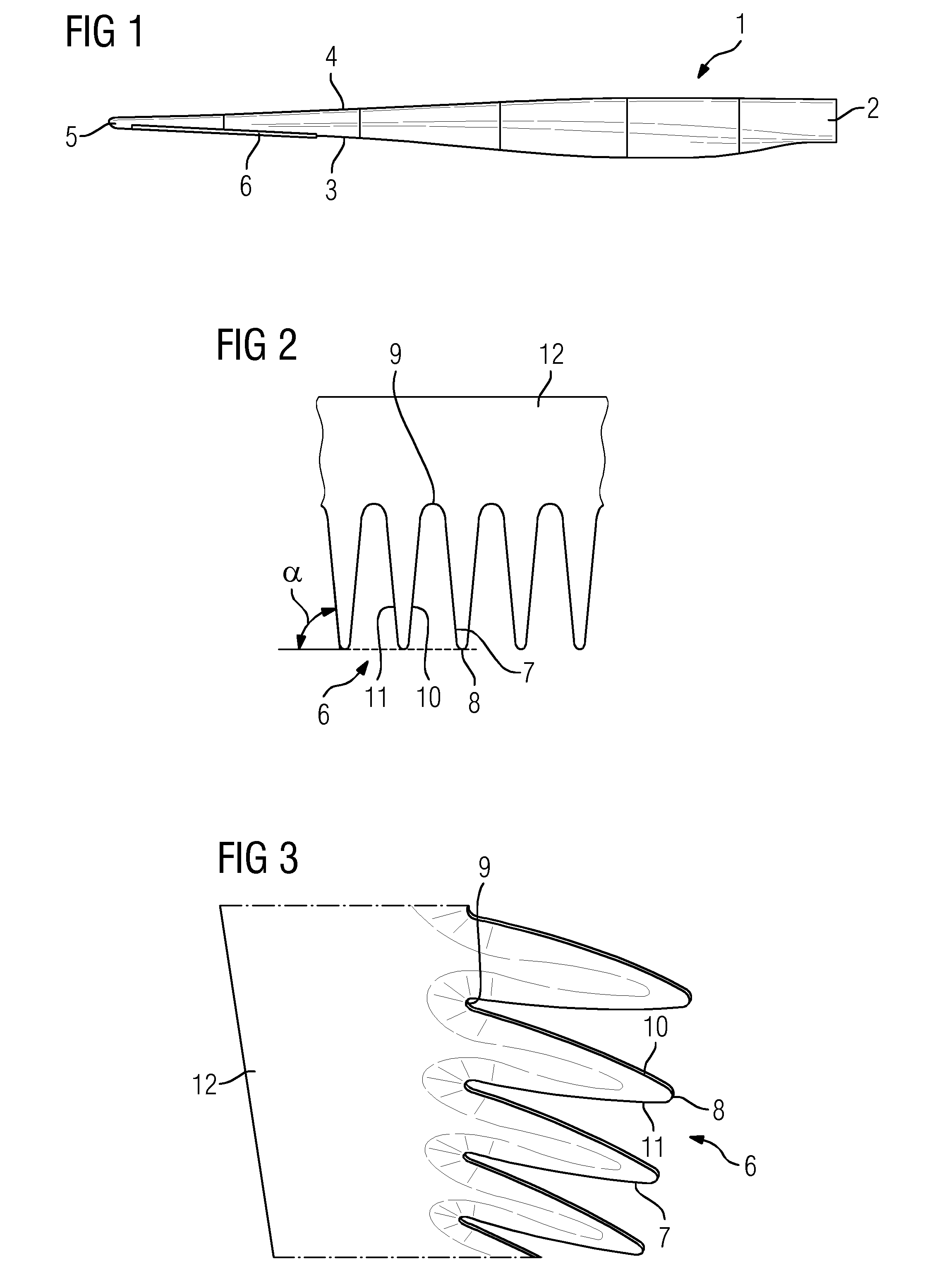
[0028]FIG. 1 is a top view of a wind turbine blade 1 with a blade root 2 where it is connected to a hub of a rotor, which is part of an electrical generator. Further the wind turbine blade 1 includes a trailing edge 3, a leading edge 4 and a blade tip 5.

[0029]At the trailing edge 3 a noise reducing device in the form of serrations 6 is attached. The serrations 6 are arranged in a section ranging approximately from 75% to 95% of the span of the wind turbine blade 1.

[0030]FIG. 2 shows a detail of the serrations 6 and FIG. 3 is a perspective view of the trailing edge 3 comprising serrations 6. In FIG. 2 one can see that the serrations 6 have a smooth shape similar to a bird feather. Typically the length of a serration is in the range of 65 mm to 300 mm corresponding to approximately 20% chord. Edges 7 of the serrations run almost parallel to the airflow in order to reduce aerodynamic noise. Consequently the serrations 6 and the trailing edge 3 include an angle between 85% and 90%.

[0031...


PUM


Abstract

A wind turbine blade having a noise reducing device attached at its trailing edge including serrations, whereby the serrations and the trailing edge include an angle between 75° and 90° is provided. The wind turbine blade may be provided wherein the angle is between 80° and 90°. In an embodiment, the wind turbine blade may be provided wherein a serration has a rounded shape at its tip and/or its notch. A wind turbine including a tower, an electrical generator with a rotor shaft and a hub to which wind turbine blades are connected, wherein the wind turbine includes wind turbine blades.

Description

CROSS REFERENCE TO RELATED APPLICATIONS[0001]This application is the US National Stage of International Application No. PCT / EP2013 / 054602 filed Mar. 7, 2013, and claims the benefit thereof. The International Application claims the benefit of U.S. Provisional Application No. 61 / 704,600 filed Sep. 24, 2012. All of the applications are incorporated by reference herein in their entirety.FIELD OF INVENTION[0002]The present invention relates to a wind turbine blade having a noise reducing device attached at its trailing edge comprising serrations.BACKGROUND OF INVENTION[0003]Wind turbine blades generate aerodynamic noise when the wind turbine operates and the rotor is in rotational movement. In general aerodynamic noise source mechanisms for lifting air-foils can be classified as follows: a) turbulent boundary-layer flow shed off of the trailing edge, b) separated boundary-layer and stalled airfoil flow, c) vortex shedding due to laminar boundary-layer instabilities, and d) vortex sheddin...

Claims


Application Information

Patent Timeline
IPC IPC(8): F03D1/06F03D9/00
CPCF03D9/002F03D1/0633F05B2240/30F05B2260/96F05B2280/4003Y02E10/72F05B2250/183F03D9/25
Inventor OLSEN, ANDERS SMAERUPASHEIM, MICHAEL J.
Owner SIEMENS AG
Why Eureka
Try Eureka