Contactless electric power feeding system

Inactive Publication Date: 2015-08-20
SOVEREIGN PEAK VENTURES LLC
View PDF7 Cites 17 Cited by
  • Summary
  • Abstract
  • Description
  • Claims
  • Application Information

AI Technical Summary

Benefits of technology

[0020]According to a preferred embodiment of the present invention, the primary feeding coil comprises a helical coil. Thereby, the primary feeding coil provides a large area in which an electro-magnetic field is distributed in an even manner. The secondary receiving coil is wound around an axial line substantially in parallel with an axial line of the helical coil, and

Problems solved by technology

Typically, a power receiving device such as a portable device incorporated with a secondary receiving coil is placed on a feeder table incorporated with a primary feeding coil to establish an electro-magnetic coupling between them, but it is known that a significant reduction in the efficiency of power transmission could occur depending on the positioning of the secondary receiving coil with respect to the primary feeding coil.
However, the moving mechanism is able to deal with only one power receiving device at a time, and recharging of multiple devices at the same or “multi recharging” cannot be achieved.
However, in this case also, in spi

Method used


Image

  • Contactless electric power feeding system
  • Contactless electric power feeding system
  • Contactless electric power feeding system

Examples


first embodiment

[0106]The primary transmission circuit 4c of the first embodiment formed a series resonance circuit because the secondary transmission circuit 3a of each portable device 3 on the power receiving end formed a series resonance circuit. However, it is also possible that the secondary transmission circuit 3a of each portable device 3 on the power receiving end forms a parallel resonance circuit. A primary transmission circuit 4c suitable for use in combination with portable devices 3 each using a parallel resonance circuit for the secondary transmission circuit 3a is described in the following with reference to FIG. 5. In the description of the circuit shown in FIG. 5, the parts corresponding to those of the previous embodiment illustrated in FIG. 4, for instance, are denoted with like numerals without necessarily repeating the description of such parts.

[0107]In the second embodiment illustrated in FIG. 5, the primary transmission circuit 4c is formed as a parallel resonance circuit con...

second embodiment

[0108]Each of the portable devices 3(1)-3(n) in the second embodiment is provided with a secondary transmission circuit 3a formed by a parallel resonance circuit consisting of a secondary receiving coil Lb1-Lbn and a secondary resonance capacitor Cc1-Ccn connected in parallel thereto. When each secondary transmission circuit 3a is formed by a parallel resonance circuit in this manner, it is preferable to form the primary transmission circuit 4a also as a parallel resonance circuit by connecting a primary resonance coil Ca in parallel with the primary feeding coil La. Suppose that the impedances of the input and output impedances of the transmission circuit unit 8 are Za and Zb, respectively, and the coupling coefficient between the primary feeding coil La and the secondary receiving coil Lb is k. The input and output impedances Za and Zb and the resonance angular frequency omega are related to one another according to the following equations.

La=Za*k / omega

Lb=Zb*k / omega

C1=1 / (La*omega2...

third embodiment

[0149]The present invention is not limited by the foregoing embodiments. the contactless electric power feeding system of the present invention is described in the following.

[0150]FIG. 18 is a perspective view of the third embodiment of the present invention. The primary feeding coil La is formed by winding a helical coil around the peripheral surface 14a of a short cylindrical retainer 14 having a diameter R to a height H. This helical coil consists of a single layer of coil. The coil wire may be similar to that of the first embodiment. Again, if desired, the primary feeding coil La may also be wound in two or more layers of coil winding.

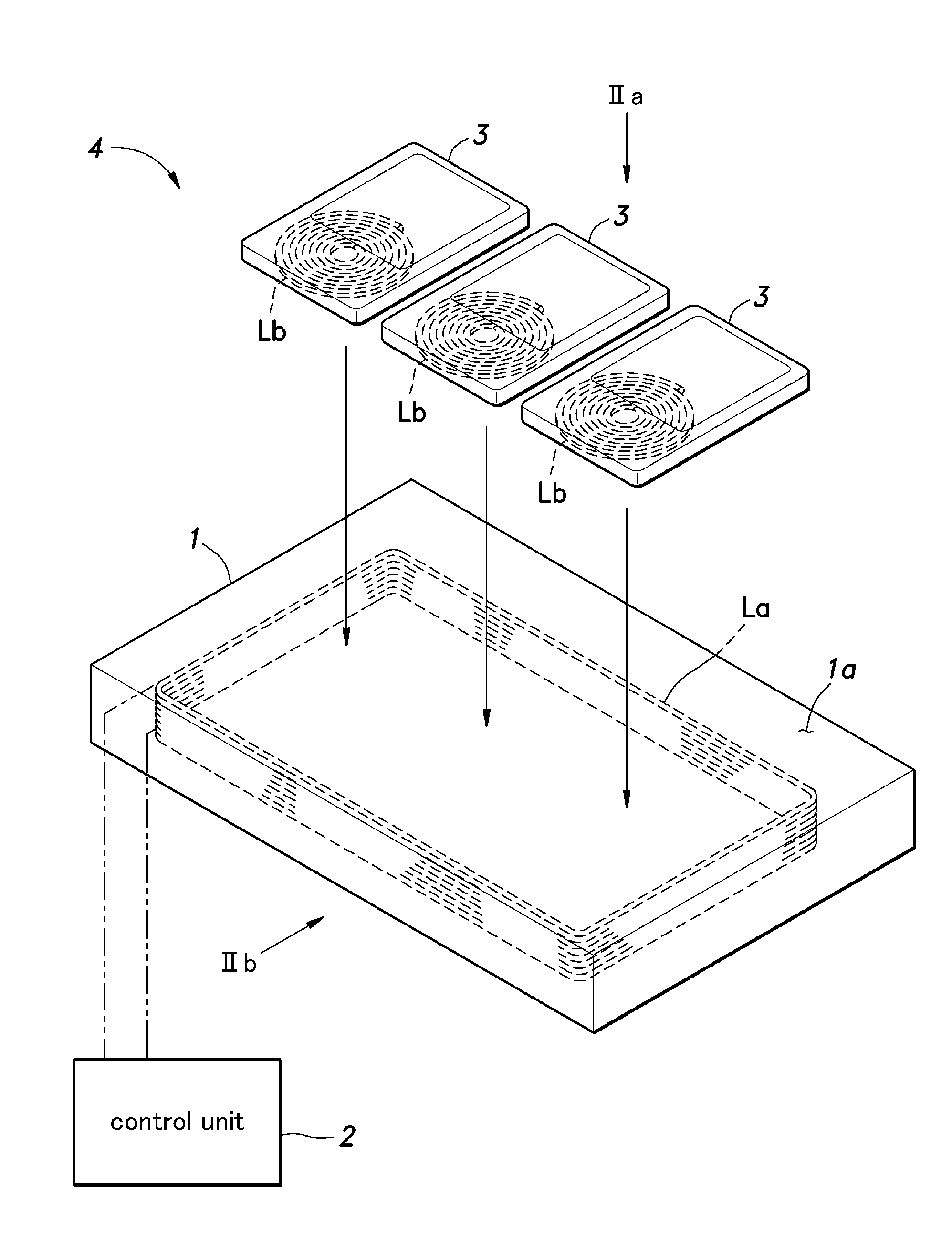
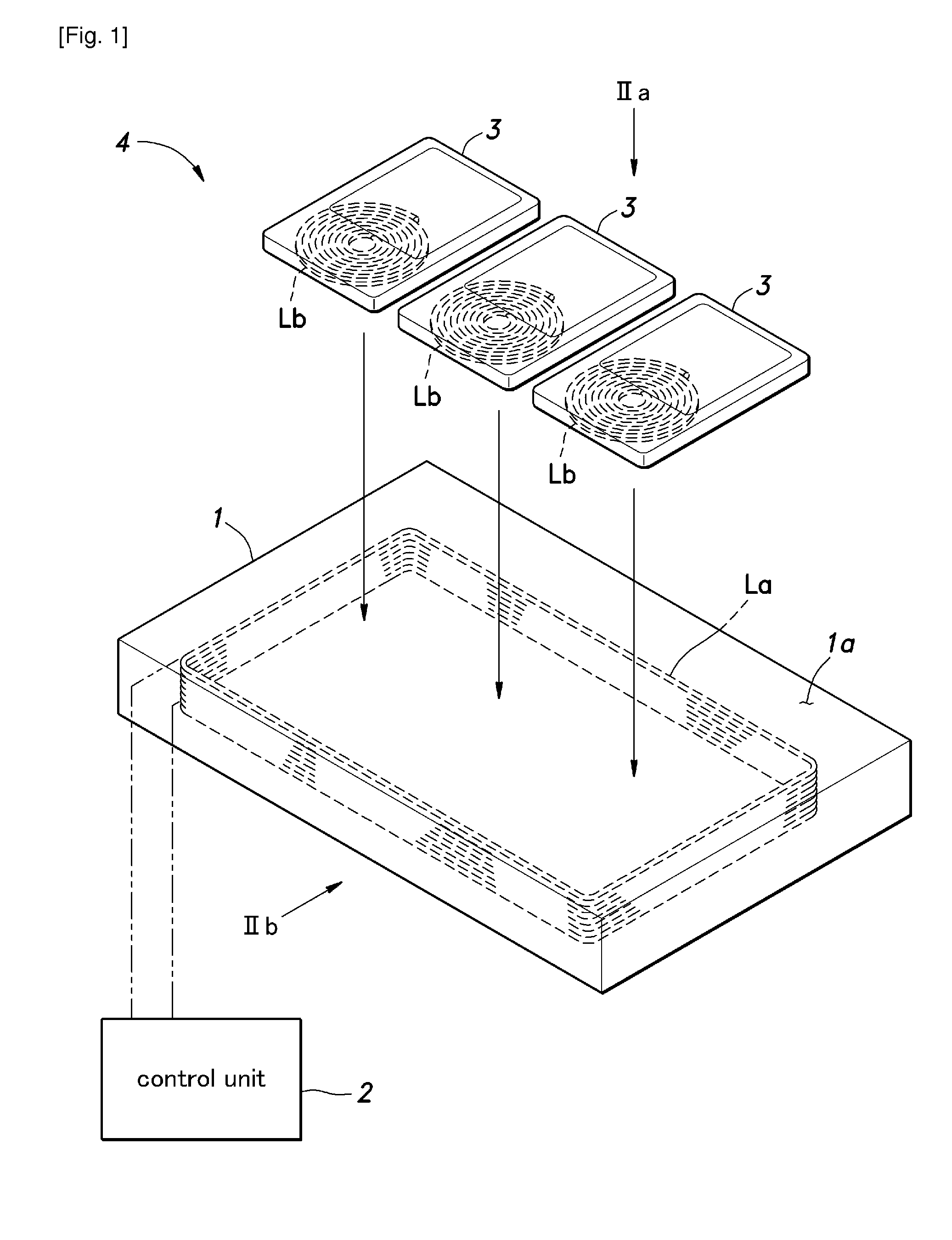
[0151]On this primary feeding coil La, in particular within an area surrounded by the helical coil as seen in plan view, three portable devices or three secondary receiving coils Lb1-Lb3 are placed. Each of the secondary receiving coils Lb1-Lb3 consists of a flat spiral coil similar to those of the previous embodiments, and the coil wire may also b...


PUM


Abstract

Provided is a contactless electric power feeding system that allows a plurality of devices to be recharged at the same time. A feeding device includes a primary feeding coil and each receiving device includes a secondary receiving coil. Each coil forms a resonance circuit jointly with a capacitor, and the two resonance circuits are electro-magnetically coupled with each other to from a transmission circuit unit. A first impedance of an input end of the transmission circuit unit is matched with a second impedance of an output end of the transmission circuit unit by using a coupling efficient between the primary feeding coil and the secondary receiving coil, and the output impedance of a power supply unit for supplying electric power to the primary feeding coil is smaller than the first impedance.

Description

TECHNICAL FIELD[0001]The present invention relates to a contactless electric power feeding system, and in particular to a technology for feeding electric power from a feeding unit to a receiving unit without requiring a physical contact between them.PRIOR ART[0002]It is conventionally known to feed electric power from a feeding unit provided with a primary feeding coil to a receiving unit provided with a secondary receiving oil by using an electromagnetic coupling between the two coils as a contactless electric power feeding. As such a contactless electric power feeding does not require any electric contacts, water proofing can be accomplished without any difficulty. Also, the problems associated with the degradation and failures of electric contacts can be eliminated, and the coupling and uncoupling between a power feeder unit and a power receiver unit can be effected in a highly simple manner. The primary feeding coil and the secondary receiving coil are typically made by winding ...

Claims


Application Information

Patent Timeline
IPC IPC(8): H02J5/00
CPCH02J5/005H01F38/14H04B5/0037H02J7/0013H01F27/23H02J50/90H02J50/005H02J50/12
Inventor DEGUCHI, FUTOSHIEGUCHI, KAZUHIROYUASA, YASUHITO
Owner SOVEREIGN PEAK VENTURES LLC
Why Eureka
Try Eureka