Fiber-reinforced composite, a component and a method

Active Publication Date: 2015-09-10
SIEMENS GAMESA RENEWABLE ENERGY AS
View PDF3 Cites 3 Cited by
  • Summary
  • Abstract
  • Description
  • Claims
  • Application Information

AI Technical Summary

Benefits of technology

[0034]According to a further embodiment, the second fibers are treated with a coupling agent. The coup

Problems solved by technology

This can be attributed to bonding failures at the interface between the resin and the fiber material when the stress direction is perpendicular to the fiber surface.
It has been

Method used


Image

  • Fiber-reinforced composite, a component and a method
  • Fiber-reinforced composite, a component and a method
  • Fiber-reinforced composite, a component and a method

Examples


Embodiment Construction

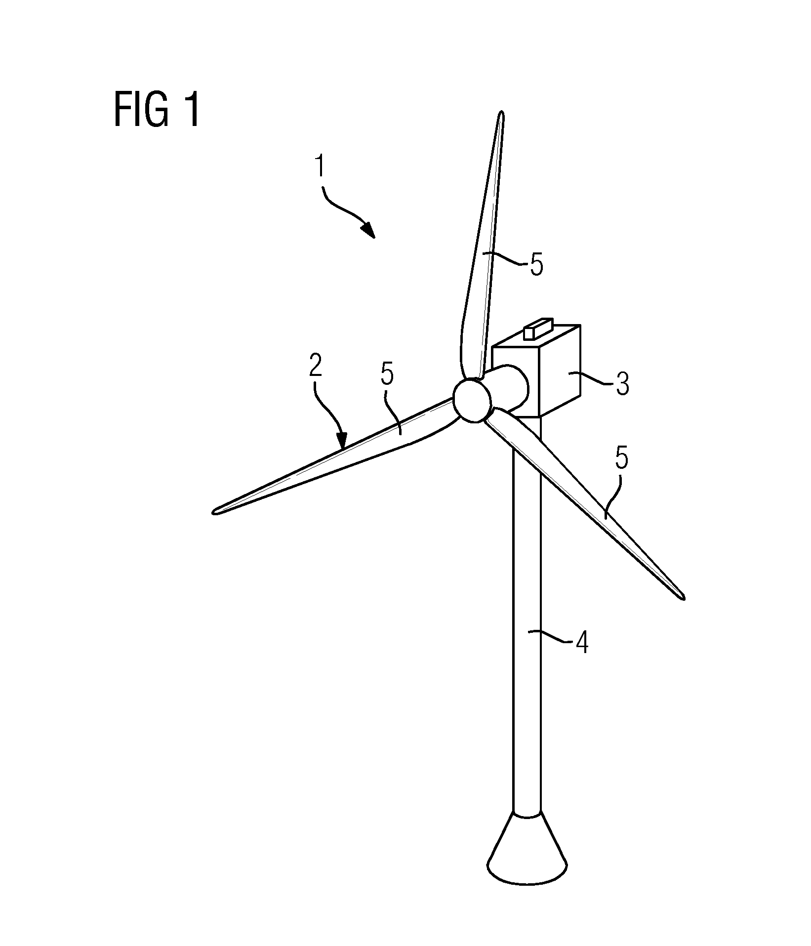
[0054]FIG. 1 shows a wind turbine 1 according to an embodiment.

[0055]The wind turbine 1 comprises a rotor 2, connected to a generator (not shown) arranged inside a nacelle 3. The nacelle 3 is arranged at the upper end of a tower 4 of the wind turbine 1.

[0056]The rotor 2 comprises three blades 5. Rotors 2 of this kind may have diameters ranging from, for example, 30 to 160 meters. The blades 5 are subjected to high wind loads. At the same time, the blades 5 need to be lightweight. For these reasons, the blades 5 in modern wind turbines 1 are manufactured from fiber-reinforced composite material. Therein, glass fibers are generally preferred over carbon fibers for cost reasons. In addition, the blades 5 may each comprise one or more core members made of a lightweight material to reduce the weight of the blades 5.

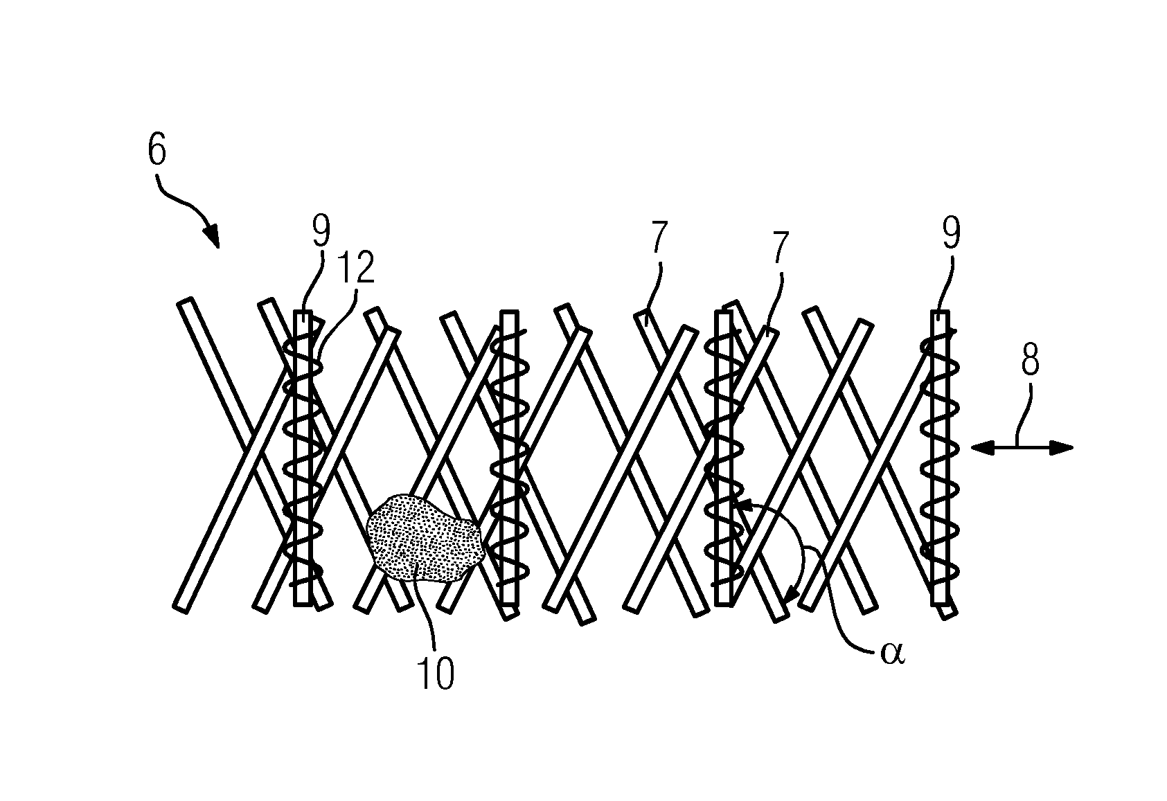
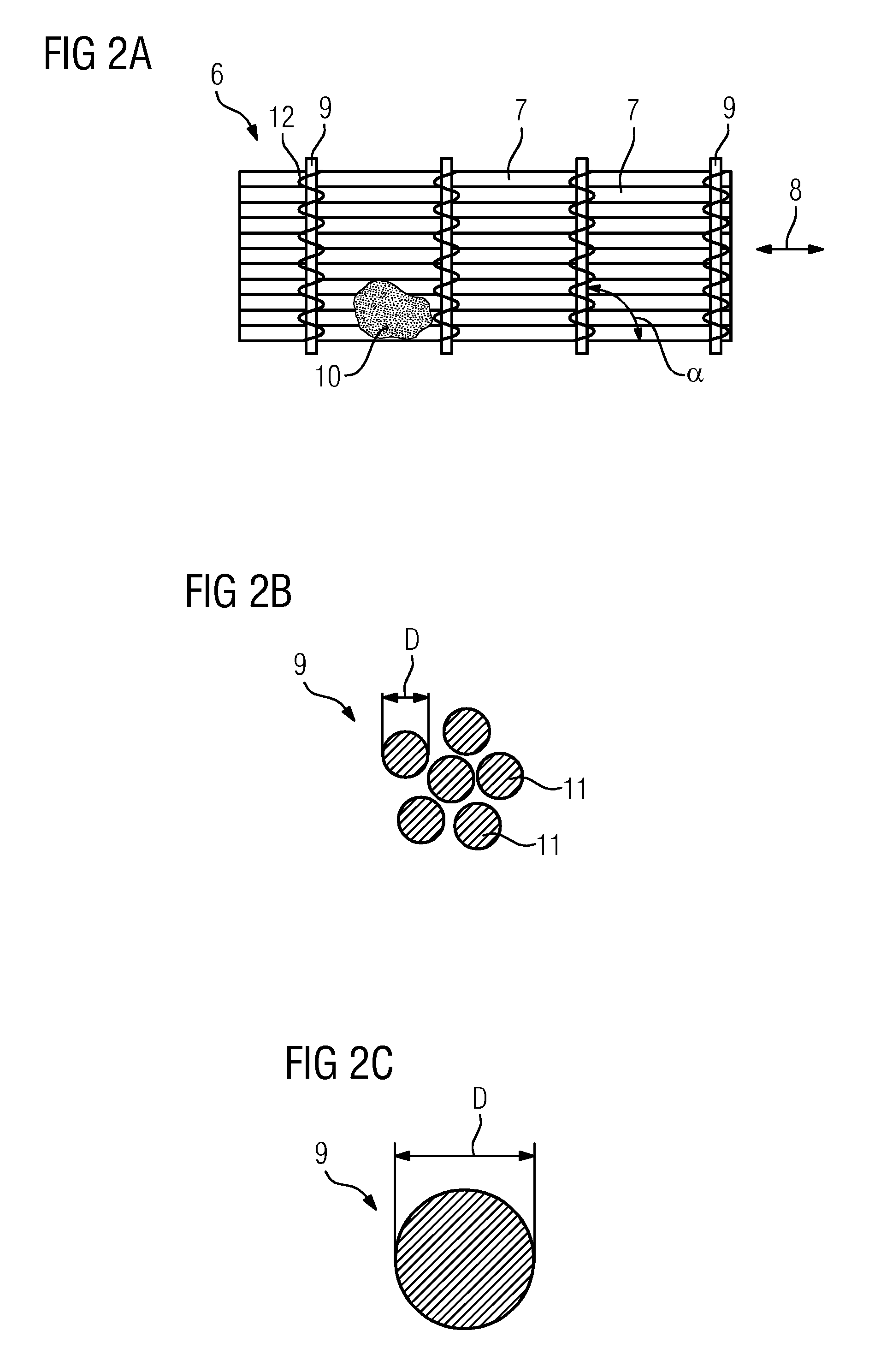
[0057]FIG. 2A shows in a top view a fiber-reinforced composite 6 according to an embodiment.

[0058]The fiber-reinforced composite 6 comprises a plurality of first fibers 7. The...


PUM

PropertyMeasurementUnit
Pressureaaaaaaaaaa
Diameteraaaaaaaaaa
Diameteraaaaaaaaaa

Abstract

A fiber reinforced composite, a component for a wind turbine and a method for manufacturing a component for a wind turbine are provided. The fiber reinforced composite includes a plurality of first fibers, the first fibers being arranged in a unidirectional or biax-configuration, a plurality of second fibers, the second fibers being arranged perpendicularly with respect to a lengthwise direction of the first fibers, and a resin impregnating the first and second fibers, wherein a E-modulus of the resin equals an E-modulus of the second fibers. Since the E-modulus of the resin and the E-modulus of the second fibers are equal, an early initiation of fatigue cracks is avoided.

Description

CROSS REFERENCE TO RELATED APPLICATIONS[0001]This application claims the benefit of European Application No. EP14158528 filed Mar. 10, 2014, incorporated by reference herein in its entirety.FIELD OF INVENTION[0002]The present invention relates to a fiber-reinforced composite, a component and a method.BACKGROUND OF INVENTION[0003]Modern wind turbine rotor blades are built from fiber-reinforced composites combined with core members, such as balsa wood or plastic foam.[0004]For example, EP 2 123 431 A1 describes a method for manufacturing a rotor blade using a vacuum-assisted resin transfer molding (VARTM)-process. In a first step of the manufacturing process, fiber material is laid onto a lower part and an upper part of a mold, respectively. The fiber material is secured in place by vacuum applied from beneath. Then, mold cores are covered in vacuum bags and are placed in the lower part of the mold together with a web (also known as a shear web). Next, the upper part of the mold, toge...

Claims


Application Information

Patent Timeline
IPC IPC(8): B32B5/12B29C70/30
CPCB32B5/12B29C70/30B32B2262/02B32B2262/0284B32B2262/0276B29K2995/0077B32B2262/0223B32B2262/0253B29K2105/108B29L2031/085B32B2262/0246B29C70/10B29C70/22B29C70/342B29C70/48B29C70/226Y10T428/24124B32B2603/00
Inventor GROVE-NIELSEN, ERIK
Owner SIEMENS GAMESA RENEWABLE ENERGY AS
Why Eureka
Try Eureka