
Nematic liquid crystal composition and liquid crystal display device using the same

a liquid crystal display device and liquid crystal composition technology, applied in liquid crystal compositions, chemistry apparatuses and processes, etc., can solve the problems of degrading display quality, difficult to control deviation from the optimum value within a particular range, and loss of the previously designed balance between the refractive index of the liquid crystal display device and the driving electric field, etc., to achieve good low-temperature solubility, low viscosity, and good resistance and voltage holding ratio against heat resistance.

Active Publication Date: 2015-09-10
DAINIPPON INK & CHEM INC
View PDF4 Cites 0 Cited by
  • Summary
  • Abstract
  • Description
  • Claims
  • Application Information

AI Technical Summary

Benefits of technology

The liquid crystal composition in this patent has low viscosity and good solubility at low temperatures. It also has high stability against changes in resistivity and voltage holding ratio even when exposed to heat and light. This results in high-speed response in liquid crystal display devices and reduces the likelihood of display failures during production. Therefore, this composition is highly useful.

Problems solved by technology

With the increase in substrate size, the mainstream injection method for injecting a liquid crystal composition into a substrate has shifted from a vacuum injection method to a one-drop-fill method (ODF); however, this leads to a problem of degradation of display quality caused by drop marks that occur at the time the liquid crystal composition is dropped onto the substrate.
Once the injection amount increases from the optimum value, the previously designed balance between the refractive index of the liquid crystal display device and the driving electric field is lost and display defects such as generation of nonuniformity and contrast failures result.
In particular, the optimum liquid crystal injection amount for small-size liquid crystal display devices frequently used in latest smart phones is small and it is difficult to control the deviation from the optimum value within a particular range.

Method used

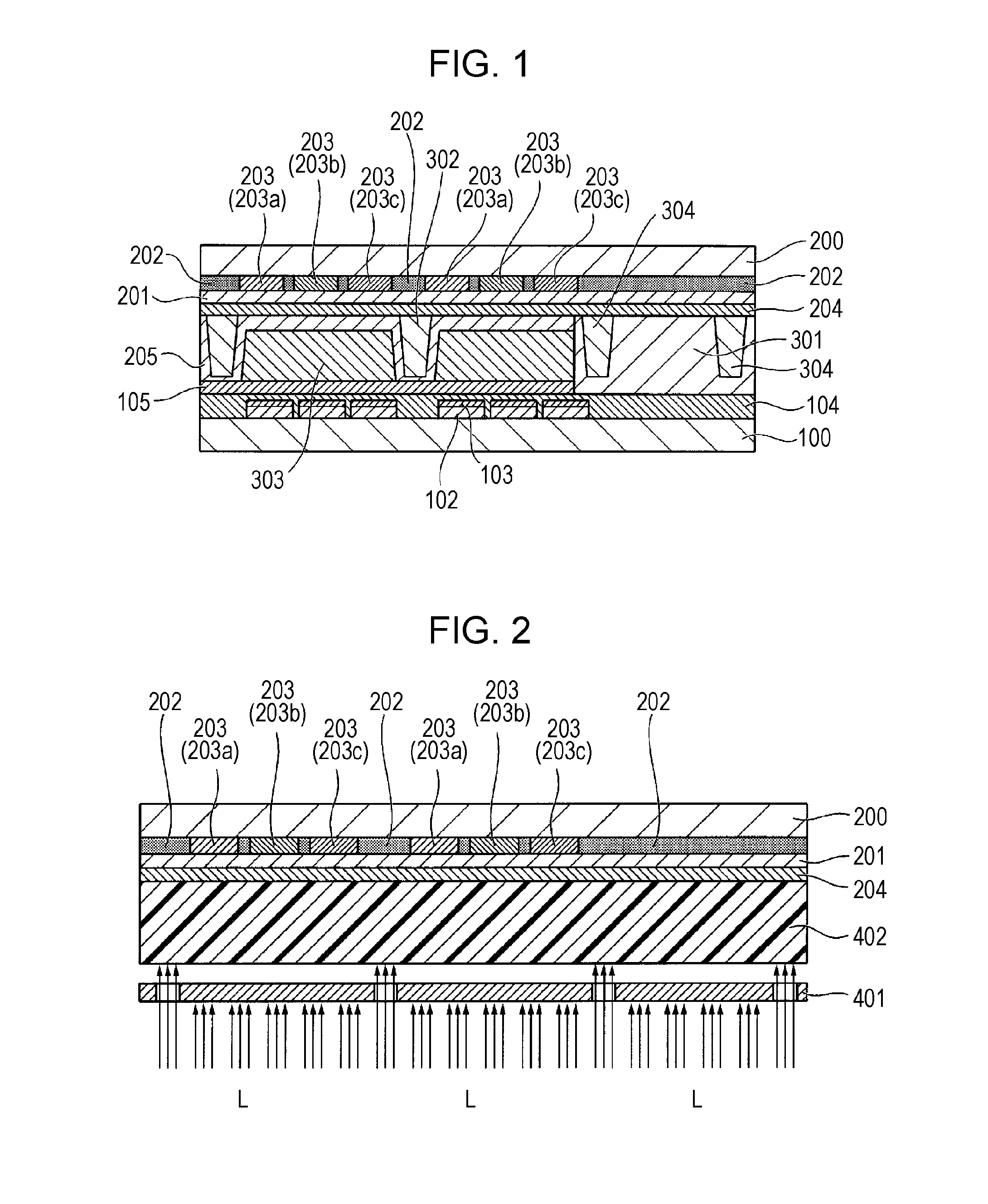

Image

  • Nematic liquid crystal composition and liquid crystal display device using the same
  • Nematic liquid crystal composition and liquid crystal display device using the same
  • Nematic liquid crystal composition and liquid crystal display device using the same

Examples


examples 9 to 14

[0464]

TABLE 5Content (%)Exam-Exam-Exam-Chemical structureple 9ple 10ple 113-Ph—Ph3—CFFO—Ph3—F7592-Ph—Ph3—CFFO—Ph3—F3-Cy-Cy-CFFO—Ph3—F645-Cy-Cy-CFFO—Ph3—F63-Ph—Ph1—Ph3—CFFO—Ph3—F33-Py—Ph—Ph3—CFFO—Ph3—F23-Cy-Ph—Ph3—Ph1—OCFFF3-Ph—Ph—Ph1—Ph3—F3-Cy-Cy-1d0FF2825303-Cy-Cy-2113-Cy-Cy-43-Cy-Cy-1d016103-Cy-Cy-1d1650d1-Cy-Cy-Ph-1151080d3-Cy-Cy-Ph-1575-Cy-Ph—Ph1—Ph-2245-Cy-Ph—Ph1—Ph-3422-Ph—Ph1—Ph-3116102-Ph—Ph1—Ph-442-Ph—Ph1—Ph-515580d3-Ph—Ph1—Ph-256TNI / ° C.76.096.076.6Δn0.1170.1300.117Δε3.904.404.16η / mPa · s11.017.911.6γ1 / mPa · s446543Initial voltage holding ratio (%)99.599.499.4Voltage holding ratio (%) after98.898.898.9heat resistance testGhosting evaluationAAAAAADrop mark evaluationAAAAAProduction facility contaminationAAAAAevaluationProcess compatibility evaluationAAAAAALow-temperature solubility evaluationAAAAA

TABLE 6Content (%)Exam-Exam-Exam-Chemical structureple 12ple 13ple 143-Ph—Ph3—CFFO—Ph3—F61182-Ph—Ph3—CFFO—Ph3—F3-Cy-Cy-CFFO—Ph3—F7355-Cy-Cy-CFFO—Ph3—F3-Ph—Ph1—Ph3—CFFO—Ph3—F3-Py—Ph...


PUM


Abstract

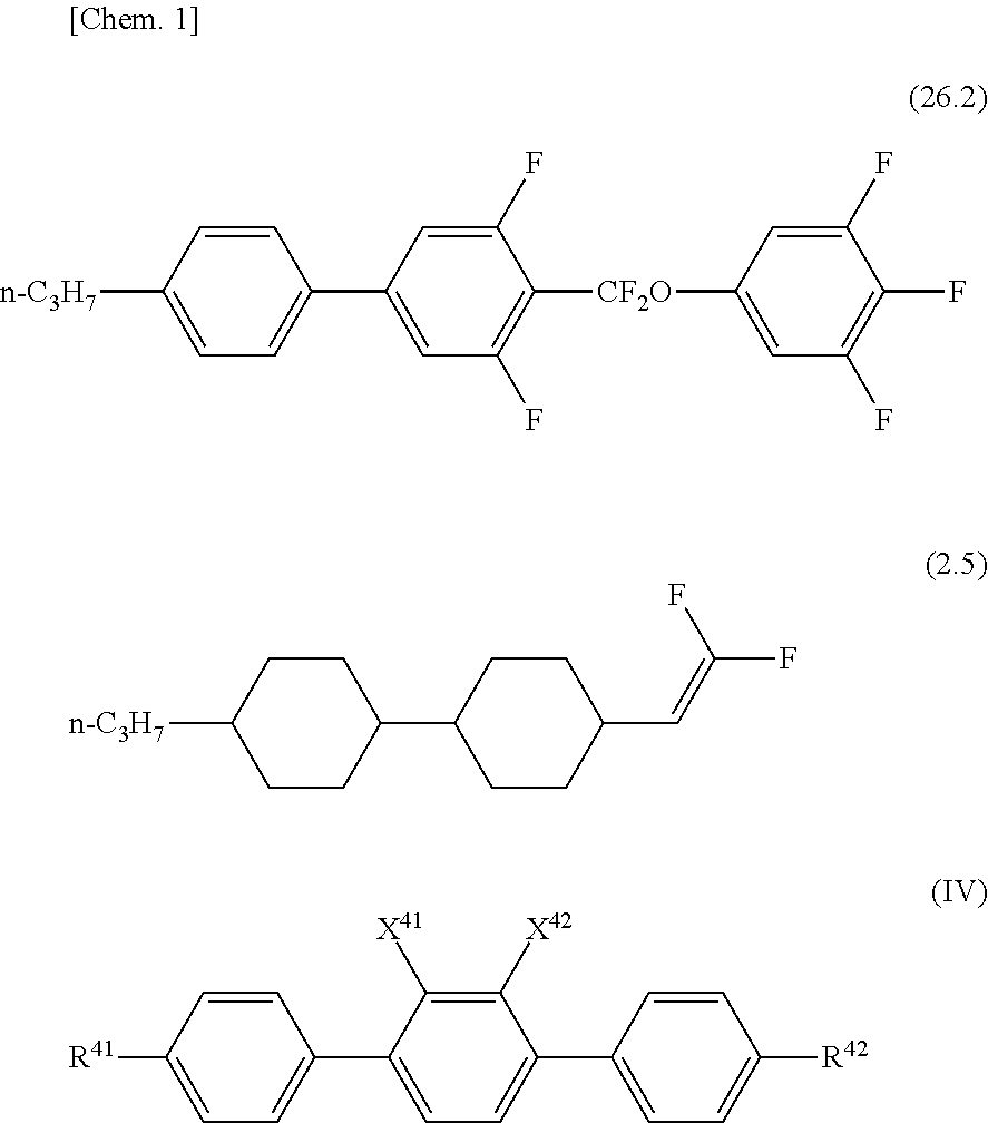
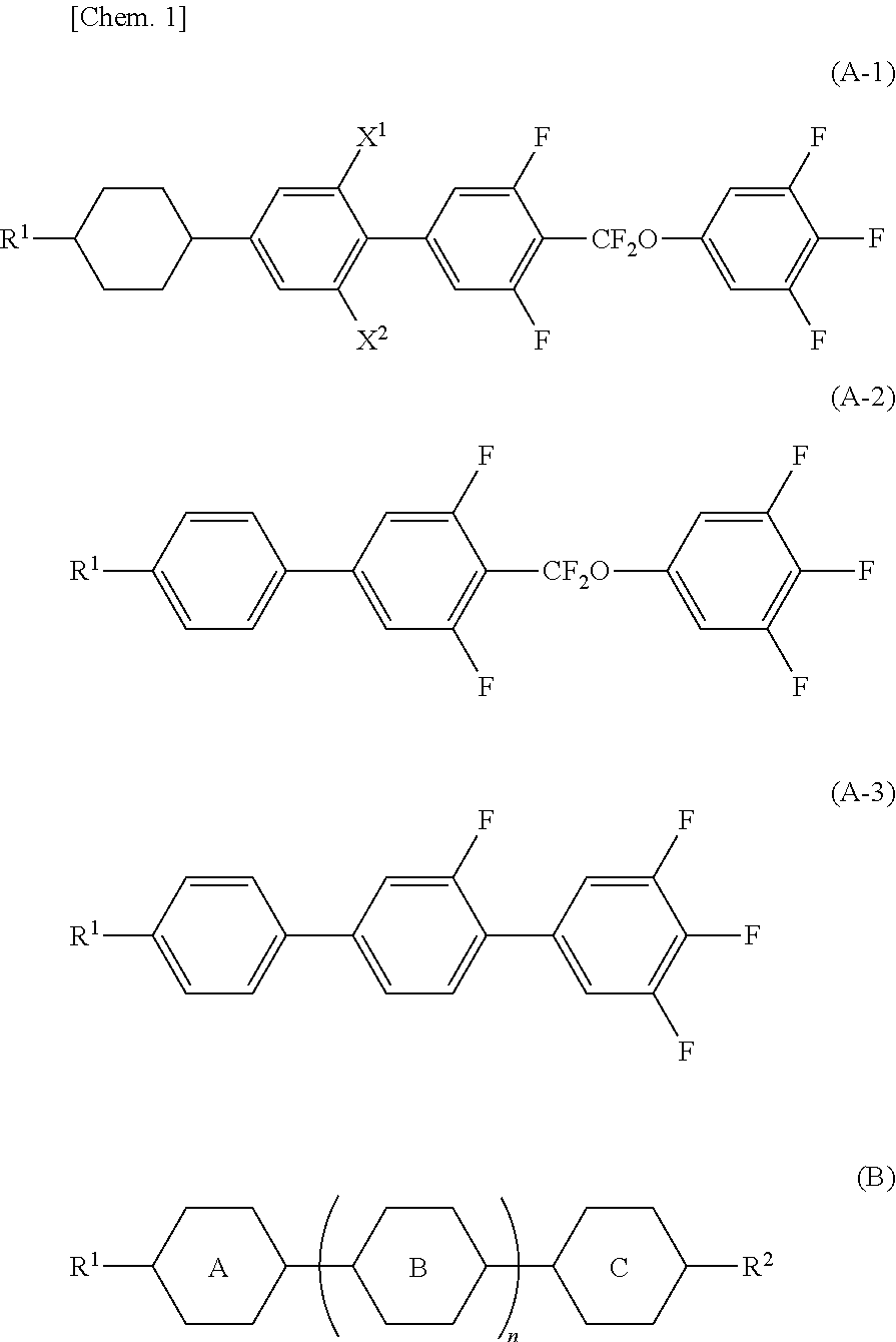
The inventor of the present invention has investigated various liquid crystal compounds and various chemical substances and found that the object can be achieved by using a combination of particular liquid crystal compounds, thereby making the present invention.In other words, provided are a liquid crystal composition having positive dielectric anisotropy, comprising compounds represented by formula (26.2) and formula (2.5) and one or more compounds represented by general formula (IV), an active matrix driving-liquid crystal display device using the liquid crystal composition, and a liquid crystal display using the active matrix-driving liquid crystal display device:(In the formula, R41 and R42 each independently represent an alkyl group having 1 to 5 carbon atoms or an alkenyl group having 4 or 5 carbon atoms and X41 and X42 each independently represent a hydrogen atom or a fluorine atom.)

Description

TECHNICAL FIELD[0001]The present invention relates to a nematic liquid crystal composition having a positive dielectric anisotropy (Δ∈) useful as a liquid crystal display material, and to a liquid crystal display device using such a composition.BACKGROUND ART[0002]Liquid crystal display devices are increasingly used in watches, calculators, various measurement instruments, automobile panels, word processors, electronic organizers, printers, computers, televisions, clocks, advertising boards, etc. Representative examples of the liquid crystal display mode include twisted nematic (TN) mode, super twisted nematic (STN) mode, and vertical alignment mode or in-plane-switching (IPS) mode that uses thin film transistors (TFTs). Liquid crystal compositions used in such liquid crystal display devices are required to be stable against external stimuli such as water, air, heat, and light, be in a liquid crystal phase in a temperature range as wide as possible around room temperature, have low ...

Claims


Application Information

Patent Timeline
IPC IPC(8): C09K19/30
CPCC09K19/3068C09K2019/3077C09K19/3066C09K19/065C09K19/44C09K2019/0459C09K2019/0466C09K2019/123C09K2019/124C09K2019/3004C09K2019/3019C09K2019/3025C09K2019/3071C09K2019/3078
Inventor KAWAMURA, JOJI
Owner DAINIPPON INK & CHEM INC
Learn More