Sintered ferrite magnet and motor provided therewith
- Summary
- Abstract
- Description
- Claims
- Application Information
AI Technical Summary
Benefits of technology
Problems solved by technology
Method used
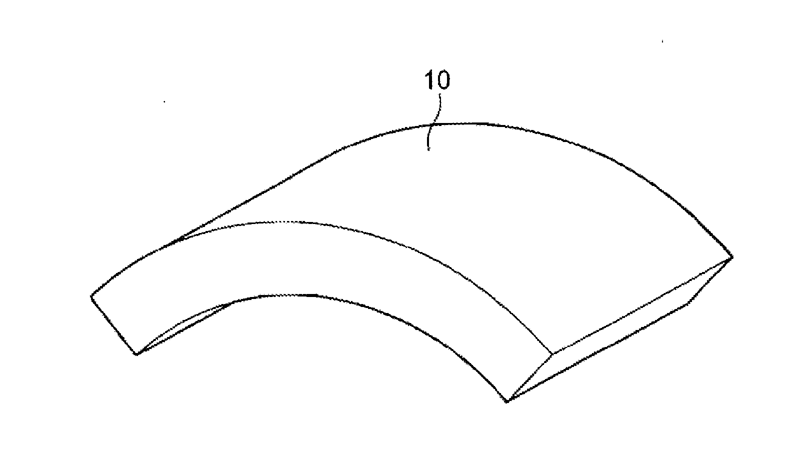
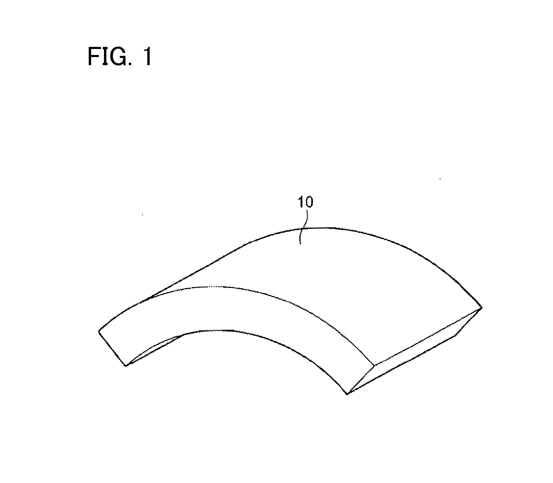
Image

Examples
example 1
[0114]1000 g of Fe2O3 powder, 161.2 g of SrCO3 powder, and 2.3 g of SiO2 powder were mixed while pulverizing the powders by using a wet attritor, and then drying and granulation were performed. The resultant powder obtained in this manner was fired in the air at 1250° C. for 3 hours, and thereby a granular calcined material was obtained. The calcined material was roughly pulverized by using a dry vibration rod mill, and thereby a powder having a specific surface area of 1 m2 / g in accordance with a BET method was prepared.
[0115]Sorbitol, the SiO2 powder, the CaCO3 powder, the MnO powder, the La2O3 powder, and the ZnO powder were added to 200 g of the roughly pulverized powder in a predetermined amount, and then wet pulverization was performed for 24 hours by using a ball mill to obtain slurry. An added amount of the sorbitol was 0.25 mass % on the basis of the mass of the roughly pulverized powder. The specific surface area of a fine powder after pulverization was 8 to 10 m2 / g.
[0116]...
PUM
| Property | Measurement | Unit |
|---|---|---|
| Grain size | aaaaa | aaaaa |
| Grain size | aaaaa | aaaaa |
| Fraction | aaaaa | aaaaa |
Abstract
Description
Claims
Application Information
 - R&D
- Intellectual Property
- Life Sciences
- Materials
- Tech Scout
- Unparalleled Data Quality
- Higher Quality Content
- 60% Fewer Hallucinations
Browse by: Latest US Patents, China's latest patents, Technical Efficacy Thesaurus, Application Domain, Technology Topic, Popular Technical Reports.
© 2025 PatSnap. All rights reserved.Legal|Privacy policy|Modern Slavery Act Transparency Statement|Sitemap|About US| Contact US: help@patsnap.com